
Custom Silicone Rubber Inner Keypad with Conductive Buttons
| Share | |
|---|---|
| Categories | Custom Silicone Rubber Inner Keypad |
| Brand | FromRubber Silicone & Plastic OEM Manufacturer |
| Design | Follow 3D Drawing Or Physical Object |
| Usage | Inner Keypad Button |
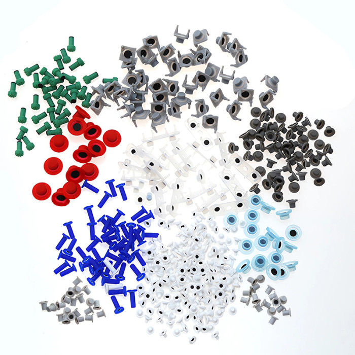
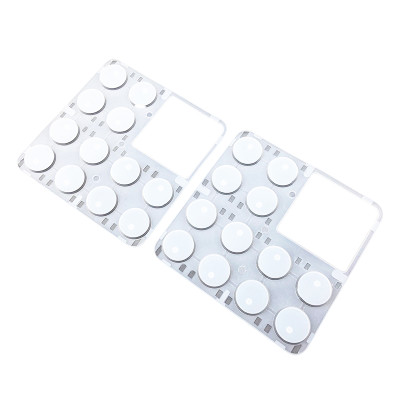
| Conduction Mode | Carbon pills, conductive ink, nickel pills or gold-plated pills |
| MOQ | 1000pcs |
| Application | Electronic Equipment |
| FOB port | Shenzhen |
| Terms of Payment | L/C, D/A, D/P, Western Union, MoneyGram, T/T, Paypal |
| Download |  |
How an Inner Keypad Works
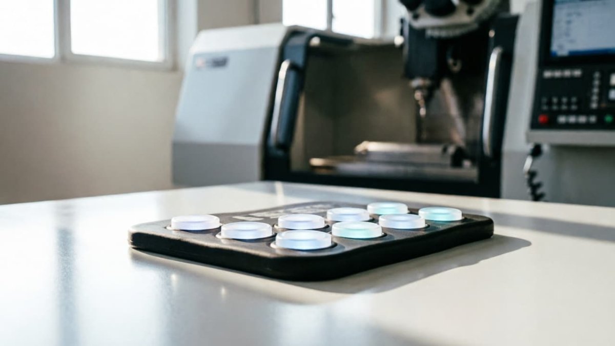
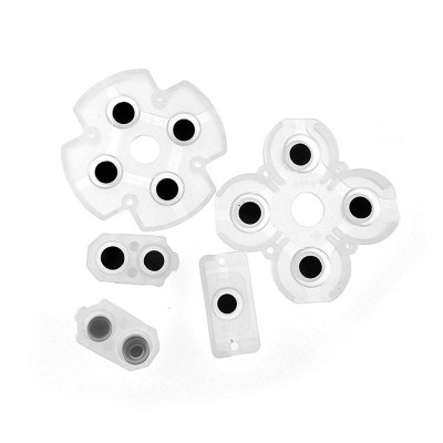
An inner keypad is the switching layer that sits behind your outer panel. The user presses a plastic, acrylic, metal, or glass fascia — the silicone underneath supplies the spring-back, the seal, and the electrical contact that closes the circuit on the PCB.
Because it is hidden, the tolerances and the contact material decide whether the finished unit feels crisp or mushy, and whether it still works after a million presses. FromRubber molds these inner keypads in-house in Dongguan, with the conductive contact selected for your circuit rather than taken off a price list.
Design Constraints That Only Apply to a Hidden Keypad
A keypad you press directly and a keypad hidden under a fascia are not the same part. On an inner keypad these four dimensions carry the whole project.
Legends sit on the fascia
Your printed overlay carries the graphics and the backlight window. The silicone only has to deliver feel and contact, so surface decoration is usually unnecessary.
0.10 – 0.15 mm floating gap
The plunger must not rest on the PCB pad. Without this clearance, housing tolerance can push the contact closed and the button reads as permanently pressed.
0.20 – 0.30 mm side clearance
Per side, between key edge and housing wall. Below 0.15 mm, thermal expansion or an off-centre press makes the key drag against the housing.
Air vent channels
Sealed key chambers trap air. Without venting between cavities, actuation force climbs and the vacuum stops the key returning to rest.
Working through the anatomy of a hidden keypad — web geometry, pill placement, sealing lip — is covered on our silicone rubber inner keypad explainer.
Choosing the Conductive Contact
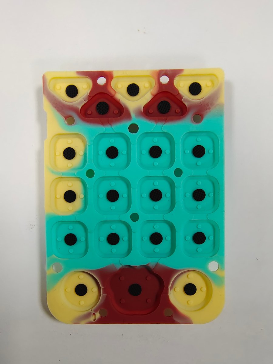
Four contact types cover almost every inner keypad project. The right one is set by your circuit's sensitivity, the environment, and the life target — not by unit price alone.
| Contact type | How it is built | Contact resistance | Typically specified for |
|---|---|---|---|
| Carbon pills (black) | Carbon-loaded silicone disc co-molded into the key base at 170 °C | 50 – 200 Ω | Remote controls, calculators, consumer panels, general instrumentation |
| Conductive ink | Carbon or silver ink screen-printed onto the cured key underside | 100 – 200 Ω | Thin profiles, non-circular contact shapes, flexible circuit integration |
| Nickel pills | Nickel-graphite metal pill, molded in or assembled to the plunger | ≤ 5 Ω | Automotive controls, industrial handhelds, low-voltage signal lines |
| Gold-plated pills | Gold over copper or silver, assembled into the key | ≤ 0.5 Ω | Medical monitors, millivolt-level instruments, dry-circuit contacts |
What the spec sheet usually leaves out
- Resistance is not the only axis. Carbon pills are the default because a logic input reads a 150 Ω contact against a 10–100 kΩ internal pull-up without difficulty. They stop being the default when the signal is analogue, millivolt-level, or exposed to oxidation.
- Shape costs money. Pills are fed into the mold by a placement jig, so a non-circular contact normally needs its own jig set. That tooling, not the pill itself, is what moves the unit cost.
- Standard pill sizes. Ø1.5 mm, Ø2.0 mm, Ø3.0 mm and Ø4.0 mm, in 0.4 – 0.8 mm thickness, cover most plunger designs.
- Drift is measurable. We specify resistance movement of no more than 20% after one million strikes, and check resistance on every piece in line rather than by sampling.
How the pill families are classified and where each one is normally specified is set out in our guide to conductive pills, their classification and use.
Specifications
| Parameter | Range | Note |
|---|---|---|
| Hardness | 30 – 80 Shore A | Held within ±2.5° of the drawing value |
| Actuation force | 80 – 500 g | Tolerance ±15 g to ±30 g depending on wall thickness |
| Key travel | 0.3 – 2.0 mm | Short travel pairs with metal domes; long travel needs a guide rib |
| Rated life | 500,000 – 5,000,000 presses | Gas-phase silica compound pushes the upper end |
| Contact resistance | 50 – 200 Ω carbon, down to ≤ 0.5 Ω gold | Measured on every unit, not by lot sampling |
| Resistance drift | ≤ 20% after 1,000,000 presses | Stable when the contact runs against gold-plated PCB pads |
| Operating temperature | −40 °C to +220 °C | Short-term exposure to 250 °C |
| Dimensional tolerance | ISO 3302-1 Class M2 | Precision grade for silicone moulded parts |
| Flash | ≤ 0.05 mm | Compared with the 0.15 mm common to standard tooling |
Values above are the ranges we build to. Your drawing sets the actual target, and we confirm it during DFM review before any tooling is cut.
How the Keypad Gets Built
DFM review
We read your drawing or measure your sample and return a quotation within 3 hours, flagging anything that will not mold cleanly.
Sample tooling
A single or double cavity sample mold is cut in our own tool room. Samples ship in 3 – 5 working days.
T1 approval
You assemble the sample into your housing and test feel, travel, and contact. We adjust from your written feedback.
Production
Multi-cavity production mold in 10 – 12 working days, then mass production with inline inspection before dispatch.
All 13 production steps — compounding, molding, trimming, post-cure, printing, laser etching, contact assembly and final inspection — run inside our own plants. Nothing is subcontracted.
How the Contact and the Key Are Verified
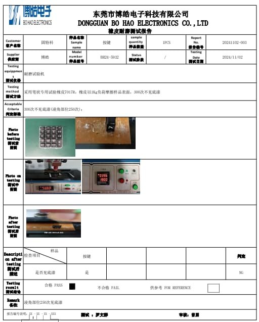
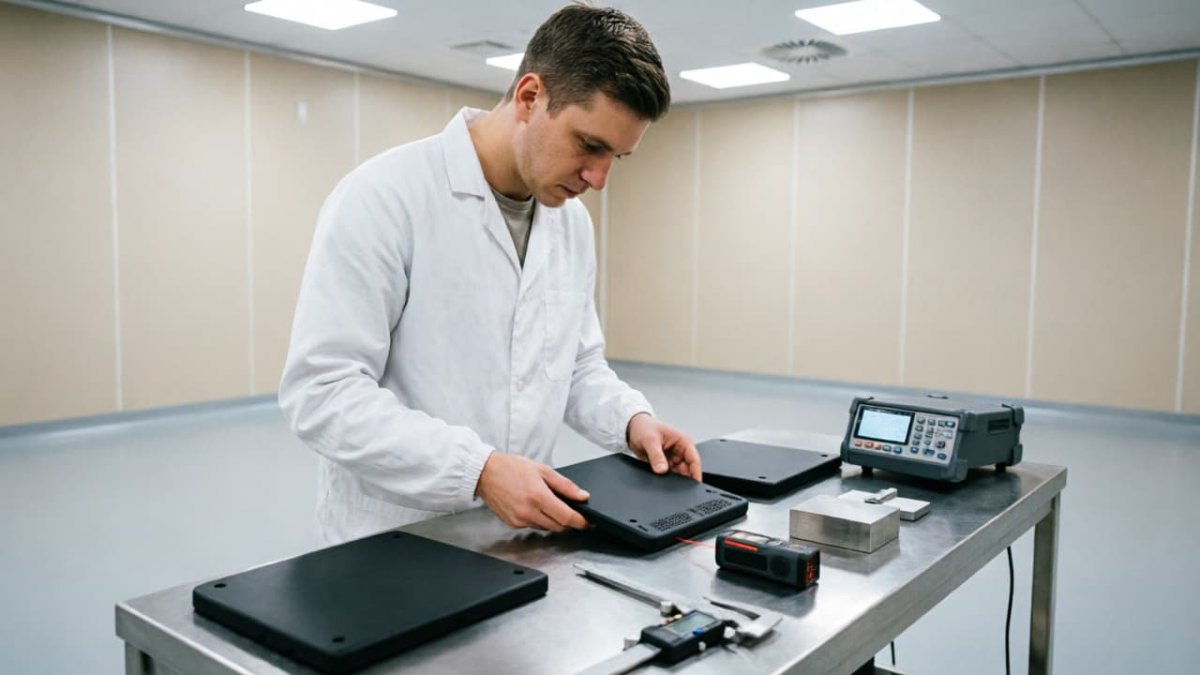
- Contact resistance — 100% checked in line against the drawing limit
- Key strike fatigue — pneumatic tester at 3 – 5 strikes per second
- Character abrasion — RCA tape, ≥300 cycles with no exposed base
- Compression set — ≤20% after 100 °C for 22 h at 25% compression
- Tear strength — ≥35 kN/m on gas-phase silica compound
- Materials compliance — RoHS 2.0, REACH SVHC, FDA 21 CFR 177.2600 on the food-contact grades
FromRubber holds IATF 16949:2016, ISO 9001:2015 and ISO 14001:2015 certification. Current material and abrasion reports are issued by SGS and independent testing laboratories.
Matching the Contact to Your Industry
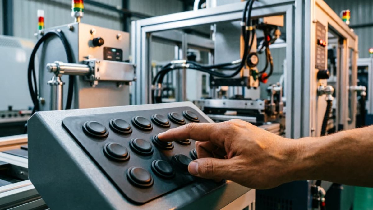
Industrial and instrumentation
Long travel and heavy press force rule out the thinnest inks. Carbon pills are co-molded into a thick-walled key, with a PU coating on any exposed surface and a nickel contact where the signal is low-voltage.
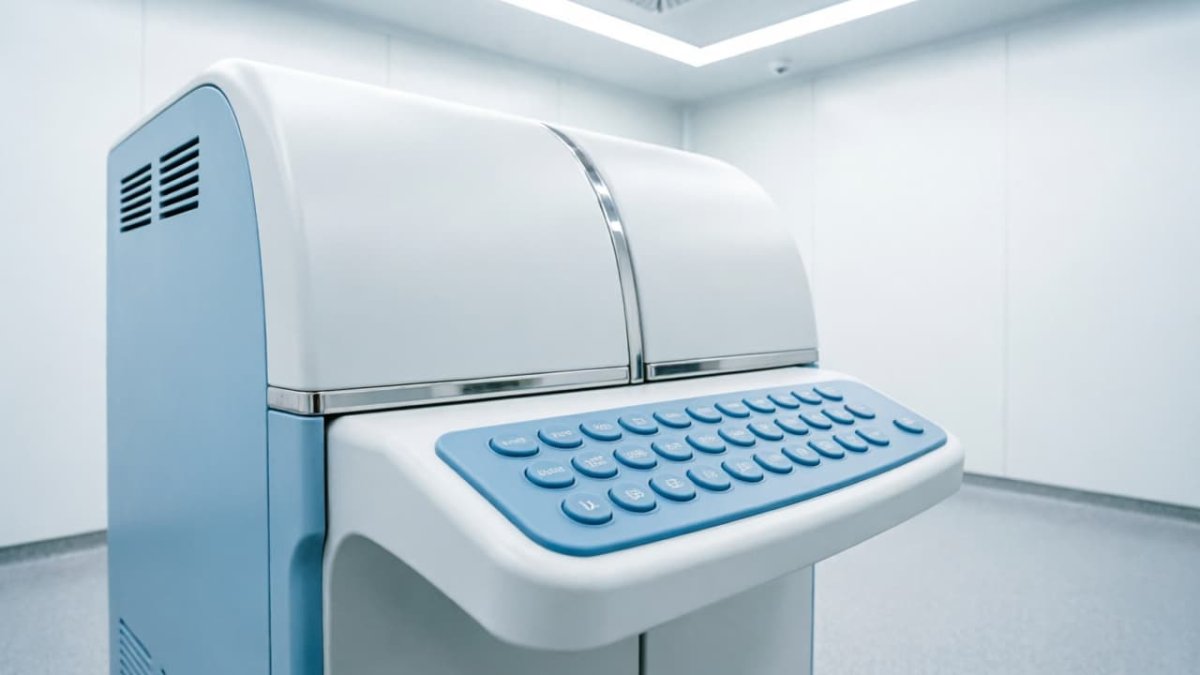
Medical and laboratory
Contact resistance has to stay stable after repeated disinfection, so gold-plated or nickel pills are specified over carbon. The key body is built in medical-grade or gas-phase silicone, and we supply the batch documentation your file needs.
Automotive
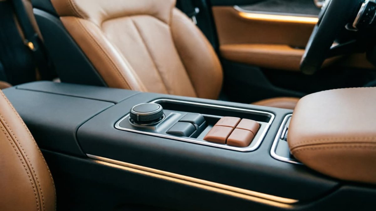
Environment and oxidation drive the choice: nickel or gold-plated contacts, gas-phase compound, low-VOC post-cure, and PPAP documentation released under our IATF 16949 system.
What Can Be Customized
Hardness and colour
30 – 80 Shore A, matched to Pantone or RAL. Hardness sets the actuation force curve, so we confirm it against your force target rather than accepting a default.
Contact material
Carbon pills, screen-printed conductive ink, nickel pills, or gold-plated pills, in the standard pill diameters or a shape developed for your plunger.
Backlighting
Translucent silicone with light-blocking base coating and laser-etched legends, at ±0.03 mm line accuracy and with no light bleed between adjacent keys.
Coating
PU, matte, or epoxy coating where the silicone surface stays exposed. Coating adhesion is tested to ISO 0 grade after the 150 °C curing cycle.
Assembly
Keys supplied with metal domes, FPC, or PCB assembled, or as the bare silicone layer if you assemble in-house.
Multi-colour molding
Two-shot molding for keys that must be colour-differentiated, with the colour boundary held to ±0.08 mm.
What to Send Us, and How Fast We Turn It Around
Send one of these
- A 3D file — STEP (.stp) or IGES (.igs)
- A 2D drawing — DWG, DXF or PDF, with the critical tolerances marked
- A physical sample, or even just your old housing and the worn keypad you are replacing
If you have no drawings, we measure the sample and reverse-engineer the tooling. This is how a 2014 POS project started, and the customer has reordered every year since.
Send these details
- Material and hardness
- Colour, as a Pantone reference
- Surface finish or coating
- Contact type, or the circuit it has to switch
- Estimated annual usage
Missing some of these is not a blocker — the engineering review resolves the open points with you. Our note on communicating keypad customization requirements lists what speeds a quotation up.
| Stage | Lead time |
|---|---|
| Quotation after receiving your file or sample | Within 3 hours |
| Sample mold and samples | 3 – 5 working days |
| Production mold | 10 – 12 working days |
| Mass production after order confirmation | 7 – 10 working days |
Tooling is paid for once and remains your property. You can have the mold moved, stored, or scrapped at any time; we keep it under free storage and warranty for two years.
Frequently Asked Questions
What exactly is an inner keypad, and how is it different from a normal silicone keypad?
A normal keypad is the part the user touches and sees. An inner keypad is the moulded silicone layer that sits behind an outer fascia, so the user presses the fascia and the silicone underneath does the switching. The feel comes from the web geometry, not from the silicone surface, which is why the tolerances in the two parts differ.
Which contact type should I choose?
If your input is read by a logic circuit, carbon pills at 50 – 200 Ω are almost always sufficient and the most economical. Step up to nickel pills when the signal is low-voltage or the environment oxidises carbon, and to gold-plated pills when the circuit measures millivolts or the contact cannot be serviced after assembly.
Can you build from a physical sample if I have no drawings?
Yes. We reverse-engineer from the sample or the mating housing, and compensate the silicone shrink rate of 2.5% to 3.5% in the mold rather than guessing. Where the customer has no drawings at all, we start from the housing the keypad has to fit.
What are the MOQ and lead times?
Standard tooling anticipates a first production batch of 1,000 pieces, and smaller trial batches can be approved case by case. Samples follow the sample mold in 3 – 5 working days, the production mold in 10 – 12 working days, and mass production in 7 – 10 working days after your confirmation.
How do you prevent keys binding or triggering on their own after assembly?
Three dimensions do the work: a 0.10 – 0.15 mm floating gap under the plunger so the contact cannot be preloaded, 0.20 – 0.30 mm clearance per side against the housing, and vent channels between key chambers so trapped air cannot hold a key down. The shrink rate is measured on the actual compound before the mold is cut.
Do you supply nickel or gold contacts for medical and automotive projects?
Yes, and for those sectors we would normally recommend them. Both contact types are supplied with the resistance limit recorded on every unit, and automotive projects are released with PPAP documentation under our IATF 16949:2016 system.
Send Your Drawing, Get an Engineering Review
- Attach a STEP, DWG or PDF file — or just a photo of your current part
- A design engineer reviews it, not a sales queue
- Reply within 3 hours: moldability points flagged, quotation attached
- Free review. Your files and tooling stay yours — NDA available
Prefer to read first? See how carbon pills compare with conductive ink, or start with our quick proofing service.
- 加载中···
Start Your Project Today!
- Phone
- *Title
- *Content
Sign Up Out Newletter
