
Why Does a Rubber Grommet Tear When Installed in a Small Panel Hole?
The fitting line stopped at 14:20. Twelve panels into the run, the same lip had split in the same place on four grommets, and the operator insisted nothing had changed. Nothing had — except the panel supplier. A 0.4 mm difference in punched hole diameter was enough to turn a comfortable push-fit into a part that tore before it seated.
Short answer
A rubber grommet usually tears in a small panel hole because the hole is smaller than the diameter the part has to pass through on its way in — not because the material is weak. The stress lands on the lip and the groove shoulder, which are the thinnest sections of the moulding. Correct the fit or the lip geometry and the same compound stops failing.
What Happens to a Grommet as It Passes Through the Hole
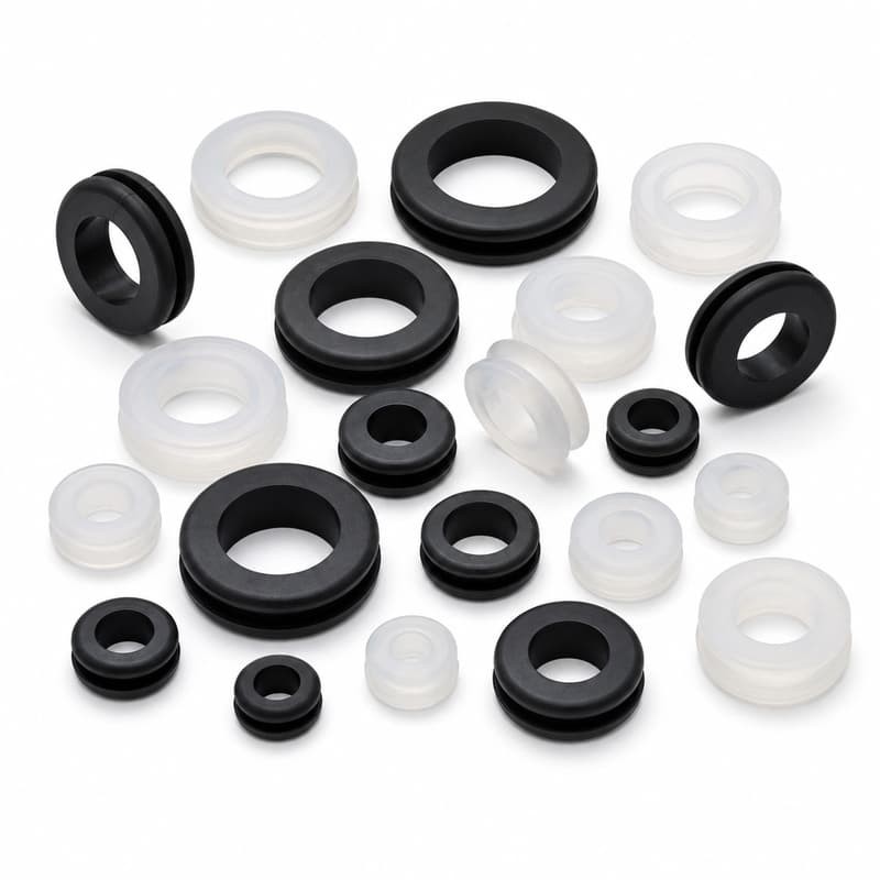
A grommet is not a washer. It is a moulded ring with a groove running around its circumference, and that groove is a clamp: the panel edge is meant to sit inside it, with an inner lip against one face and an outer lip against the other. Everything about installation is about getting the panel into that groove.
Fitting happens in a sequence, and the tear usually starts in the middle of it.
- Contact. The leading lip touches the bore and begins to deflect inward.
- Compression. The lip folds back against the body because the material has nowhere else to go.
- Groove opening. The panel edge rides up the lead-in and pushes the two groove walls apart.
- Snap-in. The groove closes over the panel edge and the lip recovers its shape.
Steps two and three are where failures begin. The lip is thinner than the body, so when it folds back it carries a far higher local strain than the rest of the part. In a well-matched fit that strain stays within the elastic range and the grommet returns to shape. In a tight fit the lip is dragged rather than folded, and the strain passes the point the compound can recover from.
That is why the split almost always appears on the lip or at the root of the groove, and almost never in the thick section of the body. The body is not doing the work. The transition is.
Why a Small Hole Raises the Stress More Than You Expect
The figure that decides installation force is not the grommet's outside diameter. It is the interference between the groove diameter and the hole.
Take a grommet with a 16 mm groove diameter going into a 15 mm hole. The panel edge has to sit in a groove that is normally 16 mm across, so the material must compress and fold by roughly 1 mm — about half a millimetre on each side. That half millimetre is absorbed almost entirely by the lip and the groove shoulder, because they are the thinnest sections in the profile.
Shrink the hole to 14 mm and the interference per side doubles. The insertion force does not double with it; it climbs much faster, because the lip has already folded as far as it can and the remaining movement turns into stretch.
Two grommets can share the same 16 mm outside diameter and behave completely differently in the same hole. One has a deep groove and a thin lip and folds easily. The other has a shallow groove and a thick, well-supported lip and fights the hole from the first millimetre. Outside diameter on its own tells you almost nothing.
The Eight Dimensions That Decide Whether It Tears
When a grommet tears repeatedly, it is worth walking the drawing in this order before reaching for a firmer compound.
| Dimension | What it does during fitting |
|---|---|
| Outer diameter | Sets the seal against the panel face. Oversized, and the lip has to fold further before the groove lines up with the edge. |
| Inner diameter | Defines how far the part can deform inward before it closes on the cable or harness. |
| Groove diameter | The real interference figure. It must be larger than the hole, and by how much matters more than any ratio. |
| Groove width | Has to track panel thickness. Too narrow and the edge cuts into the groove floor; too wide and the grommet rocks. |
| Lip thickness | The thinnest section, therefore the highest strain. Too thick and it will not fold; too thin and it tears on the fold line. |
| Overall height | Controls how much material is available to stretch before the lip starts being dragged through the bore. |
| Edge radius | A sharp corner at the groove shoulder concentrates stress. Rounding it spreads the same load across more material. |
| Flexible sealing section | Where the grommet seals on the cable. Extra wall thickness here quietly works against the panel fit. |
Moulding tolerances sit on top of all eight. A moulded rubber part carries its own dimensional window, so the worst case in a volume run is a groove at the low end of its tolerance going into a hole at the small end of the punch tolerance. The nominal fit should be designed so that worst-case pair still goes in by hand.
From the moulding floor
When grommets come back to us as torn during fitting, we ask for three things before anyone discusses the compound: the hole diameter measured at three positions, the panel thickness, and a photo of the failed part showing which clock position split.
Failures that repeat at the same clock position almost always trace back to an out-of-round hole or a burr on the punch exit, not to the silicone. Where the split location wanders around the circumference, the cause is usually the fit itself, and the drawing is what has to change.
Panel Thickness Turns the Groove Into a Clamp
Groove width and panel thickness have to agree, and gauge variation is more common than most drawings allow for.
When the panel is thinner than the groove
The grommet is not clamped. The panel edge can slide inside the groove, so the insertion load lands on one side of the lip at a time and the part can roll on its way in. Thin sheet metal with a punched edge makes this worse, because a punched edge is slightly crowned rather than square.
When the panel is thicker than the groove
The edge bottoms out in the groove and keeps going. The groove floor is now carrying a shear load it was never sized for, and the lip is stretched around a corner tighter than its natural fold radius — the classic setup for a tear that starts at the groove root and runs outward.
Where panel thickness is a range rather than a fixed value, size the groove for the top of the range and let the lip take up the difference at the bottom. Clamping by stretching the lip is survivable. Clamping by bottoming out the groove is not.
Hardness Helps, but It Is Not the Fix
The instinct when a part tears is to go softer so it folds more easily, or firmer so it resists tearing. Both instincts are partly right and mostly misleading.
Hardness describes resistance to indentation. For normal-range rubbers it is measured on the Shore A scale, and the method is standardised — see ISO 48-4 and ASTM D2240 in the sources below. Tear strength is a separate property with its own test (ISO 34-1). A compound can be soft and tear readily, or firm and resist tearing, because tear behaviour depends on the polymer, the filler system and the state of cure rather than on stiffness.
What hardness does change reliably is how much force it takes to fold the lip. A softer part needs less force and folds further, which buys installation tolerance. A firmer part holds its shape better in service, but it demands a fit that already works.
The practical rule: choose hardness for the service condition — temperature, chemical exposure, how firmly the part must grip — and solve the tear on the drawing. If a grommet only survives fitting because it was made softer, the drawing is being used as an assembly aid.
Lubrication Buys Assembly Time, Not Dimensional Slack
A compatible lubricant lowers friction between the elastomer and the panel edge, and that genuinely helps: less drag means the lip folds instead of being pulled, and the snap-in point arrives at lower force.
What it does not do is enlarge the hole. If the groove diameter is undersized for the bore, the material still has to travel the same distance. Lubricant changes how hard it is to make the part move; it does not change how far it must move. It can also hide a bad fit long enough to get parts into a panel, which is why a lubricated trial fit is not a valid dimensional test.
Two cautions worth keeping. Some lubricants, hydrocarbon-based products in particular, can migrate into a silicone part and shift its dimensions or hardness over time, so compatibility is worth checking rather than assuming. And lubricant left on the lip collects dust — its own problem on a panel that sees airflow.
Installation conditions worth ruling out first
- Burrs or a rolled lip on the punched bore, especially on the punch exit side.
- Sharp corners where the bore meets the panel face, with no chamfer.
- Pushing the grommet in at an angle rather than square to the panel.
- Pulling one side of the lip with a screwdriver or pick to start it.
- Twisting the part as it seats, which loads the lip in shear instead of bending it.
- Stretching the grommet over the harness before fitting it into the panel.
A Two-Minute Check Before the Next Fitting Run
Almost all of this is measurable at the bench, and it takes less time than reworking a panel.
- Measure the hole at three positions with a pin gauge or bore gauge, and check for ovality.
- Measure panel thickness at the same three positions.
- Measure the groove diameter and groove width on at least five parts from the box.
- Run a finger around the bore and inspect both edges for burrs under a light.
- Confirm that the durometer on the drawing matches the parts in the box.
- Check that the grommet is being fitted in the intended direction — some profiles are asymmetric.
- Fit one part by hand, with no lubricant and no tools. If it needs a tool, the fit is already outside the comfortable range.
Designing Around a Small Hole Instead of Fighting It
Where the panel hole is fixed by the enclosure — a standard punch, an existing chassis, a customer-owned tool — the grommet is the part that has to move.
The productive way to redraw it is to work backwards from the hole. Start with the bore diameter and the panel thickness, ask how much material can pass through that bore without exceeding the compound's elongation at break, and only then size the groove. That exercise usually produces several changes at once:
- Thinning the lead-in side of the lip so it folds earlier, while keeping the sealing lip thicker where it meets the panel face.
- Increasing the radius at the groove shoulder to move the stress concentration away from the thinnest section.
- Adding a short lead-in taper so the panel edge opens the groove gradually rather than all at once.
- Tightening the tolerance on groove diameter rather than on outside diameter, since groove diameter is what the fit depends on.
- Reducing overall height so there is less material to stretch before the lip seats.
Where the bore is small enough that no single-piece grommet can pass it without over-straining, a two-piece arrangement — a plain bushing with a separate retaining flange — is worth considering. It costs a second part and it removes the fold-back step entirely.
When to Change the Grommet, Not the Method
There is a point where technique and training stop helping and the drawing has to change. These are the signals:
- The hole measures small against the drawing every time, not occasionally.
- The lip is visibly stretched or blanched white before the part seats.
- Fitting needs a tool, a lubricant and two hands.
- Parts tear at the same location across different production batches.
- The groove does not span the panel thickness with the lip still proud of the face.
- Panels pass the visual fit check, but the grommet can be rotated by hand afterwards.
Any two of those together point at the fit, not at the operator.
What to Take From This
Tearing during installation is a geometric event with a material threshold. Hole size, groove diameter, lip thickness and groove width decide how far the material has to move; the compound decides how much movement it can survive. Changing one without checking the others is how a part ends up blamed for a fit that was never right.
Measure the hole and the panel first, look at the groove second, and only then argue about the material. That order resolves most cases on the first pass — and when it does not, it gives a mould shop the numbers it needs to redraw the part properly.
Sources
- ISO 34-1:2022, Rubber, vulcanized or thermoplastic — Determination of tear strength — Part 1: Trouser, angle and crescent test pieces. https://www.iso.org/standard/82445.html
- ISO 37:2024, Rubber, vulcanized or thermoplastic — Determination of tensile stress-strain properties. https://www.iso.org/standard/86892.html
- ISO 48-4:2018, Rubber, vulcanized or thermoplastic — Determination of hardness — Part 4: Indentation hardness by durometer method (Shore hardness). https://www.iso.org/standard/74969.html
- ASTM D2240-15(2021), Standard Test Method for Rubber Property — Durometer Hardness. https://store.astm.org/d2240-15r21.html