Digital Inclinometer Silicone Keypad Seal Geometry Around Buttons and Housing Openings
Week eight of a field trial, and the ZERO key on a run of digital inclinometers has started to feel gritty. The cap hesitates halfway down, returns slowly, and once in a while stays low for a full second.
Nothing inside the housing changed. The failure was designed in months earlier, when the seal lip and the button were sized on separate drawings without checking what happens where they meet. Digital inclinometer silicone keypad seal geometry around buttons and housing openings is that meeting point, and it decides whether a unit feels crisp in year three or sticky in month two.
Digital Inclinometer Silicone Keypad Seal Geometry Around Buttons and Housing Openings
A compact inclinometer asks its keypad to do two jobs at once. Every press has to reach a carbon pill on the customer's board with consistent force and a clean return, and every opening in the housing has to resist the dust and moisture that come with site use. One molded part serves both jobs, so the two argue.
Push the lip into real compression and it also resists the stroke. Open the clearance so the cap glides and dust gets a wider path to the board. Cut the opening tight and the cap rubs the wall, so the same key feels different at one end of the pad than the other. Let the keypad shift sideways and the pill lands off center, which changes contact force and seal compression together.
Two clarifications. A silicone keypad on its own does not make an instrument waterproof; sealing depends on the complete enclosure, the compression path the fasteners create, and the flatness of the surface the lip presses against. This geometry belongs in the mechanical design stage, not in a change order after the tool is cut.
How a silicone keypad seals around the buttons of a compact instrument
Button caps, connecting webs, and the return force they store
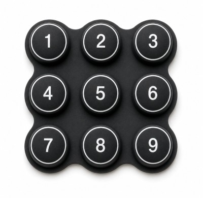
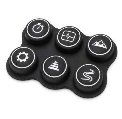
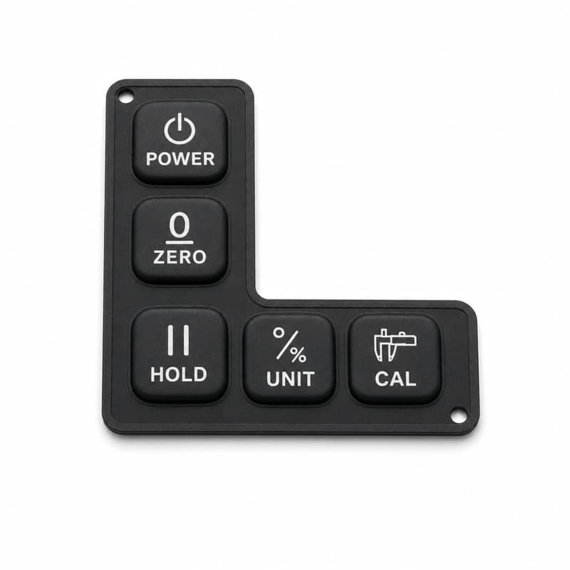
Each key is a thick cap above a much thinner web. The cap carries the legend and the conductive pill; the web is the spring. Press the cap and the silicone deforms, then the material's own recovery pushes it back. That spring is also a wall, because the web is the only continuous silicone between the button field and the outside. Reinforce it and the seal stiffens; thin it for a softer press and the cap has less stored energy to climb back after a long hold.
The perimeter seal covers the gap; the enclosure does the sealing
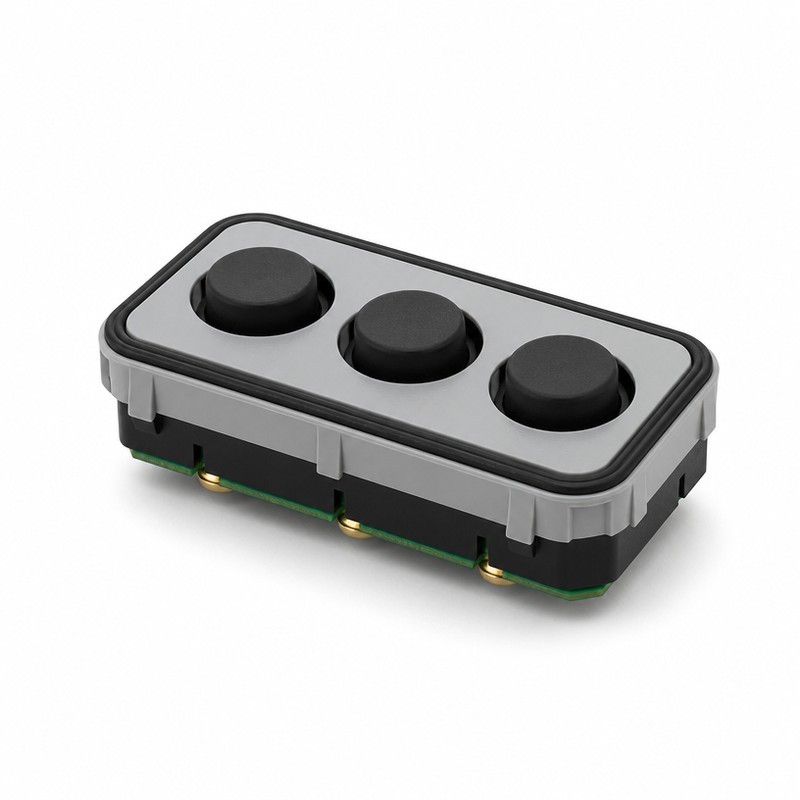
Most keypads carry a molded perimeter where the button field ends: a lip or a gasket bead that lands on a shoulder inside the housing. It closes the gap at the keypad edge, interrupts the path dust would take to the board, and locates the keypad so the keys sit under its openings. What it cannot do is seal the instrument by itself; compression has to come from screws pulling the housing closed or from a retaining frame. Warp the cover or tighten the screws unevenly and the lip follows, so compression varies around the perimeter. That mechanism sits behind why a lab sealing pass can still leak in the field.
Housing openings set the boundary conditions
Five things interact at every opening: the hole size, the wall thickness around it, the cap dimensions, the width of the lip, and any internal support touching the keypad. The opening has to allow the full stroke and still stop the cap wandering sideways. Openings are often fixed early from the overlay drawing, and then the keypad is expected to fit. It works better the other way around.
The dimensions that set button feel and seal contact
Button cap diameter or width
Cap size sets four things at once: pressing comfort, the contact patch on the board, the opening size, and how much undisturbed surface is left for the seal. Grow a cap by a millimeter and it can eat the land the perimeter lip was going to sit on; shrink it and the press feels sharp. The useful question is how much flat housing surface is left after the openings are cut.
Travel clearance, measured with the unit assembled
The cap needs a clear path through its stroke. Interference comes from housing edges, a printed overlay, internal ribs, tall components on the customer's board, and misaligned mounting features. When clearance runs out, expect sticking keys, force that differs from key to key, silicone wearing at the rub line, and slow return. Measure travel and force with the unit assembled, overlay installed, screws at final torque.
Sealing lip width and the compression area around the opening
The lip needs enough contact width to absorb housing variation and enough free height to be compressed without bottoming out. Judge it against four local conditions: the space between shoulder and mating face, how flat that shoulder is, how the compound behaves at the operating temperature, and how much the assembly tolerates. There is no universal lip width. A lip that holds on a machined aluminum shoulder at 0.4 mm compression can look marginal on a warped molded cover. Before concluding the lip needs to be taller, read the small gap clearance that stops a keypad sticking.
Transition zones between cap and web
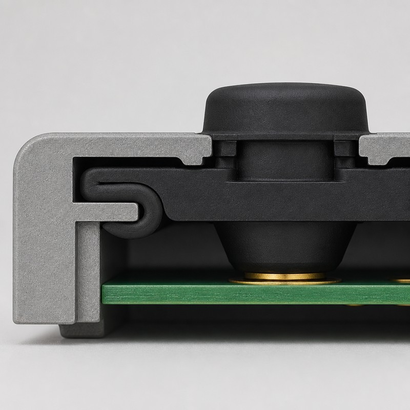
Most field failures I have looked at trace back to a transition, not to the cap or the web. Where a thick cap base meets a thin web, stress concentrates at the corner. A sharp internal radius tears after a few hundred thousand presses; a corner that is too tight in the tool fills poorly and leaves a thin wall exactly at the highest stress point. Give the transition a generous radius, then verify wall thickness on a cut sample.
Where the two design regions overlap
Draw the functional button area and the sealing boundary as two separate boxes on the keypad layout. If they overlap, the same silicone has to be soft enough to move and stiff enough to seal. Fixing the overlap with hardness alone usually trades a sticky button for a weeping lip.
What the housing opening does to the button
Opening size and lateral movement
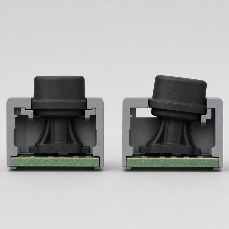
Too much clearance shows up as lateral movement: the cap tips in its hole, presses land off center, dust finds a wider path, and the key grid looks crooked. Too little clearance shows up as friction: actuation force climbs, return slows, and a rub line appears on one side of the cap. Opening and cap are one dimension pair. Set them together, with both process tolerances in front of you, and treat fit clearance between keypad and enclosure as a calculated number rather than a habit.
Wall thickness and the flatness behind the seal
A thin cover leaves the lip very little travel before the housing bottoms out, so a thick keypad frame has nowhere to develop compression. A thick wall gives room to compress but pushes the cap deeper into the housing, which changes projection and travel. A warped cover presses the lip hard at the screws and barely touches it between them, which is a leak path with no visible gap. Check flatness on molded parts after the board and supports are installed.
Internal supports that touch the keypad
Ribs, positioning posts, retaining frames, and board bosses all contact the keypad. Used carelessly, they preload the web or press a hard line under the sealing face. Model support heights with their own tolerances, because a boss listed at 0.15 mm in the file can arrive at 0.35 mm from the mold.
Common failure modes in digital inclinometer silicone keypad seal geometry around buttons and housing openings
A seal compressed past its design point raises actuation force, slows the return, and makes long presses stick. The causes are rarely exotic: not enough cap clearance, a lip that stands too proud, an opening cut small, or a tool dimension that drifted during sampling.
A seal that never reaches compression feels crisp and hides a second problem. Dust gets a wider route to the board, the keypad can migrate during assembly, and the pill drifts off its pad. That is the failure pattern behind what a too tight or too loose keypad in the housing actually means.
Uneven compression sits between those extremes. Cover warp, screw sequence, unequal wall sections, and board interference each press one part of the perimeter harder than the rest, so a single keypad carries a tight region and a loose region at once. Forced installation adds a fourth mode, because a membrane stretched or folded into place stays deformed.
| Condition at the opening | What the operator notices | Risk to the instrument | Check first |
|---|---|---|---|
| Seal compressed beyond its design point | Heavier press, slow return, sticking on long holds | Silicone fatigue at the transition, drifting contact force | Cap to opening clearance, lip free height |
| Seal never reaches compression | Crisp press, cap rocks slightly in the hole | Dust path to the board, keypad migration in assembly | Housing flatness, screw torque and sequence |
| Compression varies around the perimeter | One key feels different from its neighbor | Local leak path, lip takes a set in one area | Cover warp after assembly, support boss heights |
| Membrane folded or stretched on installation | Keys sit low or tilted, return varies by key | Permanent deformation, misalignment to the pads | Installation sequence, retention frame, entry chamfers |
Designing digital inclinometer silicone keypad seal geometry around buttons and housing openings
Start from the housing and the board layout
Pull the housing outline, button positions, board location, component heights, screw locations, and the surfaces available for sealing onto one view before a keypad outline exists. A keypad designed in isolation gets re-cut later. The DFM rules for integrating a keypad with its enclosure exist because the enclosure, the board, and the silicone share the same millimeters.
Define the functional button area
Button centers, cap diameters, stroke, actuation force, and return force belong in one block on the drawing. Fix them from the hand that will use the instrument and from the pill layout on the customer's board, then treat that block as the moving region.
Put the sealing boundary in its own region
The perimeter gets its own band, separate from the button field. Place it far enough from the buttons that pressing one does not tilt the lip, and set it against a defined housing surface with a stated compression range. Confirm the band survives the housing tolerance. Then read waterproof sealing between a keypad and a plastic enclosure for the enclosure side of the same argument.
Check the transition zone last
With both regions defined, look at the strip between them. Reject excessively thin sections, sharp corners, sudden thickness changes, and anywhere the wall carries the lip load alone. A smooth taper through that strip keeps button movement and sealing from fighting each other, and it costs nothing but a curve in the model.
Hardness, recovery, and one material body
Hardness governs compression force, flexibility, sealing response, and tactile feel. Softer silicone conforms to an imperfect housing surface but needs support to hold its shape under load, and measured to the method described in ASTM D2240, the softer compound sits at the low end of the scale. Harder silicone holds dimensions better and raises the force needed to press.
Recovery matters as much as the first reading. A sealing lip that takes a set after a month under compression stops sealing even though nothing moved. One keypad body with local thickness changes often beats two compounds, because geometry can supply the stiffness the lip needs while the web stays soft.
Stacking tolerances from the silicone to the board
Molded silicone moves: shrinkage varies with wall thickness, batches differ, tools wear, and parts can deform after demolding. ISO 3302-1 classifies rubber dimensional tolerances, and its real value is forcing a conversation about which class the seal can live with. A lip held to a tight class costs more than one designed with room for a looser class.
Housings vary too, through molding shrinkage, machining, warp, and assembly, and the board brings its own shift. Since the pill position on the customer's board is fixed by their layout, the keypad has to carry the alignment allowance. A board sitting 0.2 mm off center changes contact force on one side of the keypad and lip compression on the other.
Housing opening size and button movement after the stack closes
Add the keypad tolerance, the opening tolerance, the board position, the support heights, and the fastener take-up, and the clearance you drew is no longer the clearance you get. In a compact inclinometer the stack can eat most of it. The result is a cap that sits centered on the drawing and tilted in the housing, one side near the wall and the other showing a gap. Which side it favors tells you which feature in the stack is largest.
What to measure on the first prototype
Assembly and actuation
Assemble the first samples by hand and note how the keypad goes in: whether it drops onto its shoulder or has to be pressed down, whether any boss marks the silicone, whether the caps sit square under their openings. Then measure actuation force, return force, travel, and force at each corner of each key, with the unit closed at final torque. A key that needs noticeably more force than its neighbor has a clearance problem, not a material problem.
Sealing compression and cross sections
Check contact between lip and housing around the whole perimeter. Pressure sensitive film or a soft shim shows where compression exists and where it does not. In the cut you are looking for contact width, silicone compression, housing interference, and support positions.
Environmental validation
Environmental work follows the product requirements: moisture exposure, dust exposure, temperature cycling, and repeated assembly. Temperature cycling can be run to IEC 60068-2-14:2023, which standardizes the test rather than the pass mark. IEC 60529 describes what the two digits of an IP code actually grade. No IP rating belongs to a molded keypad by itself; it applies to a complete enclosure that has been tested and certified.
Where tooling decides the seal geometry
Tool design fixes button position accuracy, lip dimensions, web thickness, and parting line location. Where the parting line falls matters more than most drawings admit, because flash forms there. Put it on a non-sealing face and a little flash is cosmetic; run it across the lip and the same flash changes compression and key travel. FromRubber reviews a keypad drawing together with the housing and the board layout before cutting steel, because those interactions are cheaper to settle in a file.
Flash control, deflashing, post-curing, and dimensional inspection are how this geometry is held over a production run. A working inspection list covers overall dimensions, button center positions, perimeter dimensions, key height, web thickness, and the critical clearance at each cap. Prototype validation exposes housing interference, weak compression, and alignment errors while the tool can still be changed.
Design checklist for digital inclinometer silicone keypad housing compatibility
Run the drawing against these nine items before releasing it for tooling.
| Design item | Key question |
|---|---|
| Button opening | Is there enough clearance for full button travel at final torque? |
| Sealing perimeter | Does the silicone seal align with a flat housing surface along its whole length? |
| PCB position | Does the pill still land on its pad when the board sits at the edge of its tolerance? |
| Housing flatness | Is the sealing surface flat after molding and after assembly, measured on real parts? |
| Internal supports | Do ribs, posts, or bosses touch the web without preloading it? |
| Silicone hardness | Does the chosen hardness give the required return force without over-compressing the lip? |
| Tolerance stack-up | Does the summed variation still leave working clearance and usable compression? |
| Assembly process | Can an operator install the keypad without stretching or folding the membrane? |
| Environmental conditions | Are the temperature range and contamination exposure known for the whole enclosure? |
What to confirm before custom silicone keypad development
Development moves faster when these answers arrive with the request.
- Housing 2D and 3D CAD, including the wall section through each opening.
- Board layout or Gerber files showing pad or pill positions.
- Button positions, cap dimensions, and the legend layout.
- Required travel and the actuation force target for each key.
- Environmental protection requirement for the complete enclosure.
- Housing material and process, molded or machined.
- Expected assembly method and fastener torque plan.
- Required sealing region and any surface finish or printed legend.
Sealing against the enclosure
What the housing must provide before a keypad can seal anything: waterproof sealing between a keypad and a plastic enclosure.
Clearance as a number
The gap that lets a button move without letting dust in: fit clearance between keypad and enclosure.
Tight or loose, and why
Reading the symptom before blaming the mold: what a too tight or too loose keypad in the housing actually means.
Questions that come up when the seal and the button disagree
Can a silicone keypad seal an inclinometer on its own?
No. The keypad is one component in a compression path that runs from the fastener, through the housing, into the lip, and back through the retaining feature. A warped cover or uneven screw torque cannot be fixed by the lip.
What clearance should a button have in its housing opening?
There is no standard number. The clearance follows from the stack: keypad tolerance, opening tolerance, board position, support heights, and fastener take-up. Set the value after that arithmetic, then confirm it on an assembled unit.
Why does a key become sticky after a few months?
Three usual reasons. The lip is compressed past its design point and the material sets, the cap has worn a rub line against the opening wall, or contamination has packed into the clearance. A cross section of the returned part separates those cases.
Final takeaway
Seal geometry and button movement are one design problem, and drawings that separate them produce sticky keys and leak paths. Define the functional button area, define the sealing boundary, then spend the effort on the transition between them, because that strip is where stress, wear, and compression meet. Confirm the opening against a stacked tolerance calculation rather than a habit, and measure force, travel, and compression on the first assembled prototypes. Sharing the keypad drawing with the housing and board layout early, the way FromRubber handles a new project review, keeps those corrections in the file.
Sources and further reading
- IP ratings and IEC 60529, International Electrotechnical Commission: https://www.iec.ch/ip-ratings
- Rubber, Tolerances for products, Part 1, Dimensional tolerances, ISO 3302-1: https://www.iso.org/standard/62492.html
- Environmental testing, Part 2-14, Test N: Change of temperature, IEC 60068-2-14:2023: https://webstore.iec.ch/en/publication/71503