The Complete Guide to Silicone Keypad and Plastic Enclosure Fit Clearance
Silicone Keypad and Plastic Enclosure Why Fit Clearance Matters More Than You Think
Every year, thousands of electronic products are returned or reworked because of sticking keys, inconsistent button feel, or keys that simply stop working after a few months. The cause is almost always the same: the gap between the silicone keypad and the plastic enclosure was wrong from the start.
"We assembled 5,000 remote controls, and 30% of them had stuck buttons right out of the box." — Consumer electronics OEM, 2025
Whether you are designing a medical monitor, an EV charging station control panel, or a consumer remote control, the fit clearance between the silicone key and the plastic housing determines whether your product feels premium or cheap. After analyzing over 5,200 custom keypad molds across 15 years of production, we have distilled the science of fit clearance into an actionable engineering guide.
1. Anatomy of a Silicone Keypad Assembly
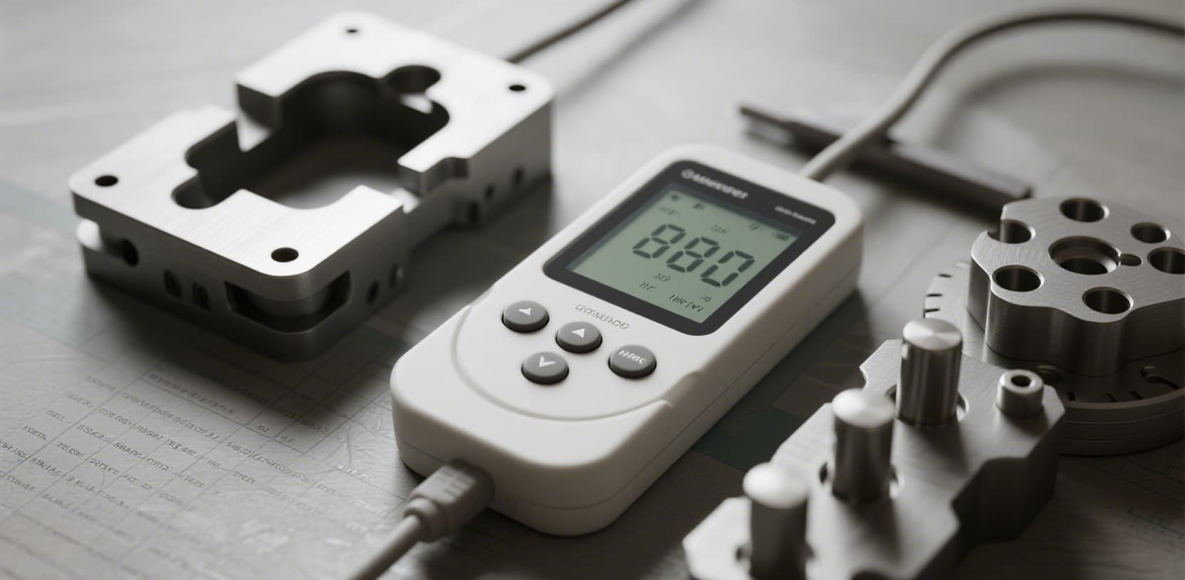
A standard silicone keypad assembly involves three primary components, each carrying its own manufacturing tolerances. The art of fit clearance is managing how those tolerances stack up.
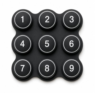
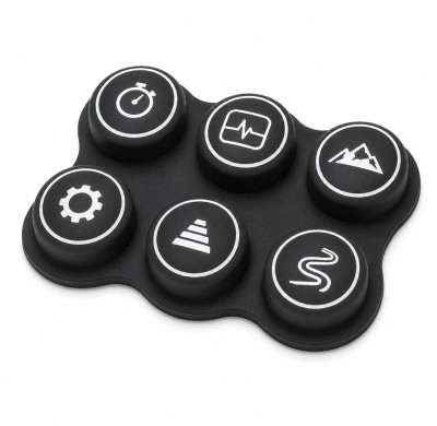
Component 1 — Silicone Keypad: Compression-molded from HCR or LSR. Includes the key top, actuation web (skirt), and conductive carbon pill.
Component 2 — Plastic Enclosure: Injection-molded from ABS, PC, PC/ABS, etc. Contains precisely cut key openings and locating features.
Component 3 — PCB Assembly: The electronic substrate with gold-plated contact pads or dome switches.
2. The 3 Root Causes of Sticking Keys
Industry data consistently points to three primary failure modes that account for over 90% of keypad sticking issues.
2.1 Improper Fit Clearance
The gap between the silicone key periphery and the plastic enclosure wall is the single most critical dimension. Improper clearance alone causes over 90% of post-assembly key sticking problems.
| Surface Condition | Recommended Clearance (Per Side) |
|---|---|
| Bare silicone + bare plastic | 0.10 – 0.20 mm |
| Silicone spray-coated only | 0.20 – 0.25 mm |
| Both silicone and plastic coated | 0.25 – 0.30 mm |
| Electroplated plastic housing | 0.30 – 0.40 mm |
Design tip: Always add 0.05–0.10 mm tolerance buffer beyond the theoretical minimum to account for production variation.
2.2 Tolerance Stack-Up and Material Shrinkage
Silicone rubber shrinks by 3% to 5% during molding. This shrinkage is not uniform. Plastic injection molding adds its own variability. The combination can easily exceed your clearance budget if not managed early.
2.3 Off-Center Alignment and Locating Features
Best practice: incorporate at least two asymmetric locating pins on the silicone keypad for foolproof assembly orientation.

3. Actuation Force, Travel and Tactile Feel
| Parameter | Typical Range | Application Guidance |
|---|---|---|
| Actuation Force | 80 – 300 gf | 80 gf for consumer; 250+ gf for gloved operation |
| Key Travel | 0.30 – 1.5 mm | Short for membrane; long for tactile preference |
| Snap Ratio | 1.3 – 1.6 | Higher ratio = crisper click feedback |
4. The Hidden Problem: Silicone Oil Bleeding
Uncured low-molecular-weight siloxanes migrate to the surface over time and condense on PCB gold fingers. Specify post-curing at 200 °C for 4 hours minimum and use platinum-cured silicone for high-reliability applications.
5. DFM Checklist for Fit Clearance
- Have we specified the correct clearance class?
- Have we accounted for post-cure shrinkage? (3–5%)
- Does the keypad have at least two asymmetric locating pins?
- Is the key well draft angle at least 1 degree?
- Is the silicone web thickness between 0.40–0.60 mm?
- Have we included vent grooves (0.30 mm depth)?
- Is post-curing specified in the manufacturing plan?
- Do we have a defined tolerance budget?
- Is the actuation force consistent across all keys?
- Has the supplier performed a DFM review before tooling?
6. Case Study: From 15% After-Sales Rate to 0.5%
A European consumer electronics brand had a 15% warranty return rate due to sticking keys. After our redesign with 0.15 mm per-side clearance, asymmetric locating pins, and vent grooves, returns dropped to 0.5% — saving €240,000 annually.
7. Key Industry Standards
| Standard | Relevance |
|---|---|
| ISO 3302-1 Class M2 | Dimensional tolerance for rubber keypads |
| DIN ISO 3302 M1 | Tighter precision for medical/automotive |
| IEC 60529 (IP Rating) | Ingress protection for sealed assemblies |
| UL 94 | Flammability rating for plastic enclosures |
8. Frequently Asked Questions
Q: What is the minimum clearance for bare silicone inside an ABS housing?
A: 0.10 mm per side lower bound. 0.15 mm recommended.
Q: My keypad has inconsistent actuation force. What should I check?
A: Check web thickness uniformity, off-center alignment, and PCB contamination.
Q: Can LSR give tighter tolerances than HCR?
A: Yes. LSR holds ±0.03–0.05 mm; HCR achieves ±0.08–0.15 mm.
9. Get Your Fit Clearance Right From Day One
Silicone keypad fit clearance is the difference between a premium product and one that generates returns. Eliminate sticking keys before they reach production.
FromRubber has been engineering custom silicone keypad and plastic enclosure solutions for over 15 years. Send your CAD for a free DFM review