Angle Grinder Silicone Keypad Failure Problems in High-Vibration Working Environments
A grinder keypad can pass every static test in the laboratory and still fail on site. The reports read the same way each time: the tool sometimes needs two presses, the brake key has fired by itself when the tool was set down, and the panel feels different from the one on the shelf. In almost none of these cases has the silicone torn. Vibration does something less obvious than breaking a part, and it is worth naming it properly before replacing a compound.
The silicone is usually not the part that fails first
At the vibration levels a grinder produces, the acceleration is not what destroys a moulded elastomer. Silicone has no notch sensitivity worth speaking of and no fatigue limit that a keypad web approaches in normal service. What vibration changes is everything around the material: how the contact closes, how the panel stays attached, and where the key sits at rest. Those three effects account for most keypad complaints on vibrating tools, and each one has a different fix.
The vibration magnitudes involved are large enough that the tool is treated as a workplace health risk in its own right. ISO 5349-1 specifies how human exposure to hand-transmitted vibration is measured and evaluated, and the UK regulations built on that framework set a daily exposure action value of 2.5 m/s² A(8) and an exposure limit value of 5.0 m/s² A(8) for hand-arm vibration. Those numbers describe what a hand receives from the tool; they are a useful reminder of how much oscillatory energy is passing through the same handle that carries the keypad.
Failure one: the contact stops closing the same way every time
A key at rest is a small mass on a silicone spring, sitting some fraction of a millimetre above the switching surface. Forced vibration turns that assembly into a driven oscillator. If the excitation includes energy near the natural frequency of the key on its web, the key face moves relative to the element beneath it, and the contact can make and break many times during what the operator experiences as a single press.
The consequences differ by switching method. A metal dome sits free until pressed and closes over a small area, so it is the most sensitive to relative motion, and the result is contact chatter that the controller may read as several presses or as none. A conductive carbon pill rides on the silicone and carries the damping of the web with it, which changes the failure signature from chatter to resistance instability: the contact still closes, but not at the same resistance every time, and it drifts as the pad wears.
Why the problem often shows up on one key only
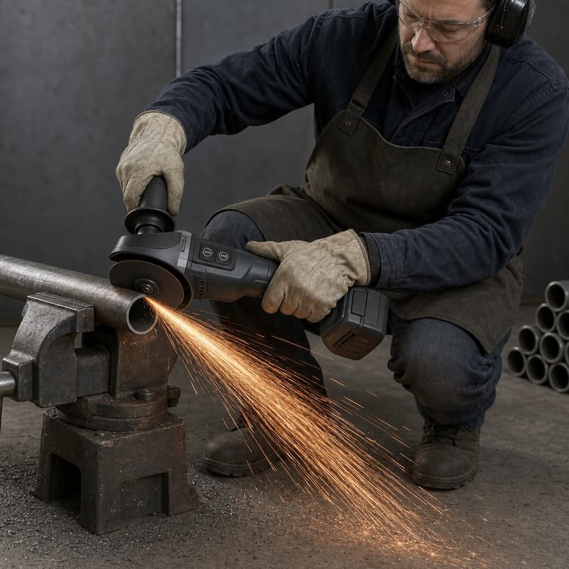
Not every key on a panel sees the same mechanical environment. The key closest to the motor end sits on a stiffer section of housing and is excited differently from the key nearest the battery. Where a panel has one key that misbehaves and the rest are fine, the cause is usually local: a shorter web, a heavier key boss, a thinner section under the key, or a switching element that sits slightly higher on that position. A single compound change for the whole keypad will not correct a position-specific problem.
Failure two: the softest part of the assembly is the attachment
Between a vibrating housing and a vibrating printed circuit board, the keypad flange is the only compliant layer. Any relative movement between the housing and the keypad has to be absorbed somewhere, and it is absorbed at the flange, in the form of small sliding displacements repeated many times a second. This is fretting, and it has two signatures worth looking for.
The first is adhesive creep or shear in whatever holds the flange down. Pressure-sensitive tapes are the common choice and the common failure: the tape does not fail suddenly, it relaxes, the flange lifts a fraction, and the panel begins to move. The second is wear on the housing itself, where the keypad edge has polished a line into the plastic. Either way the seal that was designed for a stationary interface now has a moving one, and the gap that opens is the same gap that lets abrasive dust in.
Where a keypad flange is retained by pinching between two housing halves or by a hook tab rather than by adhesive, the failure mode moves again. Pinch retention resists shear well and tolerates temperature badly, because the plastic relaxes under sustained load. The practical check is not whether the panel is loose in your hand but whether the flange is still carrying its intended pre-load after a thermal cycle in the assembled tool.
Failure three: the rest position drifts, and the force band goes with it
Sustained compression plus elevated temperature is the standard recipe for compression set in any elastomer, and a grinder keypad sits in exactly that condition. The grinder body warms during use, the panel is held slightly compressed by its own retention, and over months the flange and the web root stop returning to their original dimensions. Two outcomes follow from the same change.
If the key rest position drops, the element underneath may end up permanently close to its closing point, and the panel starts registering inputs that were never pressed. If the flange relaxes instead, the key line moves away from the switching plane and the operator has to press further, which users describe as a key that has gone soft even though the measured actuation force may be unchanged.
Compression set is measured by ISO 815-1 or by ASTM D395, and the detail that matters here is the test temperature. The room-temperature figure describes how the compound behaves on a bench. The figure at the tool's real body temperature describes how it behaves in the handle. Where a programme is chasing a rest-position problem on a vibrating tool, the elevated-temperature number is the one worth asking for.
Pre-load is the variable nobody measures
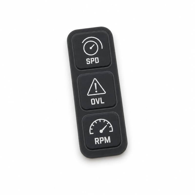
Ask three people on a programme what the key pre-load is and you will usually get three answers, because it is a consequence of the housing, the flange thickness, the retention method and the switching element height rather than a line on the keypad drawing. It is worth turning into a number. Measure the gap between the key face and the switching surface in the assembled, torqued, thermally soaked tool, then set a minimum for it. Without that minimum, vibration, temperature and compression set are all working on an unknown starting condition.
Qualify by test, and test the assembled panel
IEC 60068-2-6 describes sinusoidal vibration testing as a standard procedure for determining whether components and equipment withstand specified severities of vibration, and it is the usual reference when a keypad needs a qualification method rather than an argument. Two details decide whether the test predicts anything.
The first is the specimen. A bare keypad in a fixture is not the assembly. Vibration qualification is only meaningful when the keypad is mounted in the real housing, over the real switching element, retained by the real method, because all three of those change the response. The second is the measurement. Running the sweep and then checking function afterwards tests whether the part survived. Monitoring contact resistance continuously during the sweep tests whether the contact ever misbehaved, which is the actual failure mode on a vibrating tool.
Adding a thermal soak before the run closes the loop. A panel that has already spent a defined period compressed at body temperature is closer to a used tool than a freshly built one, and the rest-position drift shows up in the vibration results instead of appearing in a customer complaint a year later.
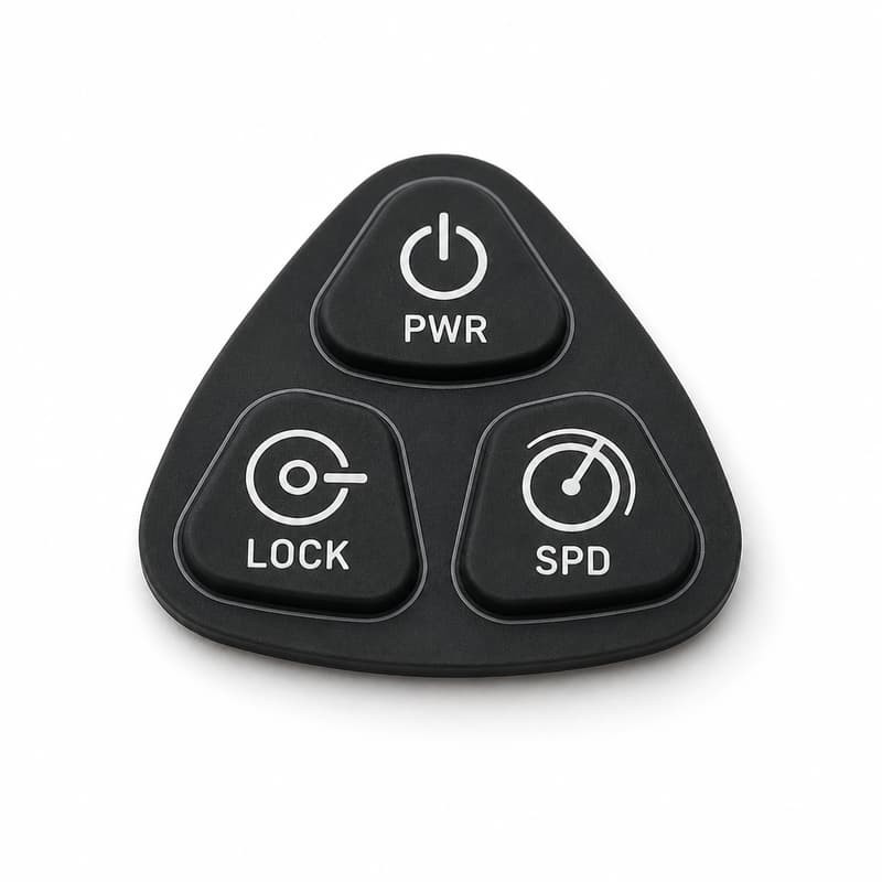
Three design moves that reduce vibration sensitivity without touching the compound
Give the key that must not self-actuate its own outline and its own force group, so it is not sharing a web profile with the keys next to it. Shorten and stiffen the web behind any key that sits near a housing resonance, rather than thinning it to raise travel. And move the switching plane closer to the key face by reducing the air gap deliberately at the design stage, so that the distance vibration has to cover before closure is small and known.
What to specify before a vibrating-tool programme is released
- Key pre-load as a measured minimum in the assembled, torqued, thermally soaked tool.
- Force band per key group, with the lock or brake key placed in its own group.
- Compression set to ISO 815-1 or ASTM D395 measured at the tool body temperature, not room temperature.
- Retention method stated explicitly, with the plastic relaxation that will occur under sustained load accounted for.
- Vibration qualification to IEC 60068-2-6 on the assembled panel, with contact resistance monitored during the sweep.
- Thermal soak before the vibration run so rest-position drift is included in the result.
- Tolerance class to ISO 3302-1 for the keypad, so that the pre-load does not depend on which cavity made the part.
A grinder panel that behaved differently on the bench and in the hand
The report described a brake key that occasionally triggered during cutting. On the bench, mounted in a fixture and swept by hand, nothing reproduced. Mounted in the housing, held in the realistic grip, and run on the real machine, the same key closed repeatedly within a couple of seconds of the tool reaching load.
Measured with the housing open, the gap between that key face and its element was smaller than the gap on the two neighbouring keys. The parts were inside the drawing, but the drawing allowed a range of pre-load that the assembly could not hold: the section of housing under the brake key was thinner than under the others, so the flange sat deeper once the fasteners were torqued. Reprofiling the web to a shallower stand-off solved it, and the compound was left alone. Two earlier attempts had changed hardness, and neither had touched the real variable.
The lesson generalises well. Where a keypad misbehaves on only one position of a vibrating tool, look for a local difference in the stack before looking at the compound. Where misbehaviour moves between positions from unit to unit, look at the tolerance band rather than the nominal design, which is what ISO 3302-1 exists to make explicit.
The silicone keypad supplies the web, the key outline, the contact element and the sealing geometry, and it has to match the board it closes against. The board, its pad layout and its switch selection belong to the customer's electronics design, and FromRubber works to that drawing.
Questions that come up when a vibrating tool starts misreading keys
Does vibration physically damage a silicone keypad?
Not usually at the material level. The failures that get reported are functional rather than structural: contact chatter, unstable contact resistance, loosened retention and a shifted rest position. A torn keypad on a vibrating tool is far more often a symptom of a moulding or assembly defect than of vibration itself.
Would a metal dome be more reliable than a conductive pill on a vibrating tool?
It depends on what the tool has to survive. A metal dome gives a sharper break-over and lower resistance but closes over a small area and reacts to relative motion, so it can chatter. A carbon pill is damped by the silicone and tolerates a particle on the pad better, but its resistance is higher and less stable. The useful comparison is a monitored vibration run on the assembled panel, not a datasheet comparison.
How do I find a housing resonance without a modal test?
Run a slow sinusoidal sweep to IEC 60068-2-6 across a wide band while monitoring contact resistance on each key. Frequencies where one key misbehaves and its neighbours do not are the ones worth attention. It is not the same information as a modal analysis of the housing, but for a keypad decision it is usually enough to identify which positions need a stiffened web.
FromRubber (Dongguan Bohao Electronic Technology Co., Ltd.) moulds custom silicone keypads for hand-held tools and industrial equipment, and reviews web geometry, pre-load and retention against the housing and switching plane before tooling. The technical notes above come from that review work and from the standards listed below.
Related reading
Sources
- [1] ISO 5349-1:2001, Mechanical vibration - Measurement and evaluation of human exposure to hand-transmitted vibration - Part 1: General requirements. https://www.iso.org/standard/32355.html
- [2] UK Health and Safety Executive, The Control of Vibration at Work Regulations 2005: daily exposure action value of 2.5 m/s² A(8) and exposure limit value of 5.0 m/s² A(8) for hand-arm vibration. https://www.hse.gov.uk/vibration/hav/regulations.htm
- [3] UK Health and Safety Executive, hand-arm vibration exposure calculator guide, including exposure points per hour and the time to reach the exposure action value. https://www.hse.gov.uk/vibration/hav/calculator-guide.htm
- [4] IEC 60068-2-6:2007, Environmental testing - Part 2-6: Tests - Test Fc: Vibration (sinusoidal), the standard procedure for determining the ability of components and equipment to withstand specified severities of sinusoidal vibration. https://webstore.iec.ch/en/publication/544
- [5] Intertek, scope of IEC 60068-2-6 Test Fc sinusoidal vibration testing and the mechanical robustness it assesses. https://www.intertek.com/automotive/standards/iec-60068-2-6/
- [6] Measurlabs, EN 60068-2-6 sinusoidal vibration testing procedure over a specified frequency range and duration. https://measurlabs.com/products/sinusoidal-vibration-testing/
- [7] iTeh Standards, EN IEC 62841-2-3:2021, particular requirements for hand-held grinders including the rated no-load peripheral speed limit of 80 m/s. https://standards.iteh.ai/catalog/standards/clc/f2639a9a-2e9e-4301-8b8b-36086fac65ce/en-iec-62841-2-3-2021
- [8] ISO 815-1:2014, Rubber, vulcanized or thermoplastic - Determination of compression set - Part 1: At ambient or elevated temperatures. https://www.iso.org/standard/61761.html
- [9] ScienceDirect topic overview, Compression set: why residual curative and continued cross-linking in the compressed state produce permanent set that cannot be reversed. https://www.sciencedirect.com/topics/engineering/compression-set
- [10] SItech, metal domes vs conductive carbon inserts in silicone rubber keypads, including contact resistance and feedback differences relevant under dynamic conditions. https://www.sitech-corp.com/blog/the-pros-and-cons-of-metal-domes-vs-conductive-carbon-inserts-in-silicone-rubber-keypads/
- [11] Interchange Electronics, conductive carbon pills vs metal dome keypads, comparing tactile feedback sharpness and actuation character. https://interchangeelectronics.com/conductive-carbon-pills-vs-metal-dome-keypads/
- [12] ISO 3302-1:2014, Rubber - Tolerances for products - Part 1: Dimensional tolerances, classes M1 to M4 for moulded rubber products. https://www.iso.org/obp/ui/#iso:std:iso:3302:-1:en