What CNC Operators Wish About Their Silicone Keypad Layout
CNC Machine Control Keypad Design
Ask a CNC operator what they would change about their machine pendant, and the answers are strikingly consistent: keys too close together, no tactile feedback when a key registers, function keys buried in the wrong corner, and legends that wear off after a year of swarf and coolant. These are not preferences - they are usability defects with measurable costs in cycle time, scrap, and operator fatigue. This article explains what CNC operators actually wish about their silicone keypad layout, the ergonomic numbers behind those wishes, and how a machine control OEM can turn operator feedback into a better keypad specification.
1. Why CNC Operators' Opinions on Silicone Keypad Layout Matter
A CNC pendant keypad is used thousands of times per shift, often with gloved or oily hands, in a vibration-heavy environment, with the operator looking at the spindle rather than the keys. Every ergonomic defect in the silicone keypad layout is multiplied by that usage intensity. A 1 mm key-spacing error that causes 2% mis-presses sounds trivial until a mis-press sends a tool into the workpiece. Operator feedback is therefore engineering data: it describes where the layout fails under real usage, and it predicts field service calls and machine downtime.
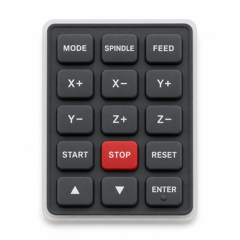
Machine tool OEMs that collect structured operator feedback on keypad ergonomics typically find the same top five complaints: accidental activation of adjacent keys, inadequate tactile confirmation, inconsistent key-to-key feel, hard-to-find emergency and axis keys under time pressure, and legend wear that makes keys unreadable. Each complaint maps to a specific silicone keypad design parameter, which means each is fixable before tooling. This article walks through all five, with the numbers that separate a good layout from a bad one.
2. The Layout Complaints CNC Operators Report Most
In operator surveys and maintenance interviews, five complaints recur across machine brands and control generations:
- Adjacent-key mis-presses. When key pitch (center-to-center spacing) drops below about 16 mm, gloved thumbs reliably hit two keys at once. Operators consistently ask for more spacing between axis jog keys, which carry the highest mis-press cost.
- Dead feel. A snap ratio below 1.3 makes it impossible to tell whether the key registered without looking. Operators report "double-tapping" keys because the first press gave no tactile event.
- Inconsistent force across the keypad. When actuation force varies by more than about ±30 gF from key to key, operators distrust the whole panel and press everything harder.
- Poor emergency layout. The stop and axis keys need fixed, muscle-memory positions; operators resent layouts that move them between machine revisions.
- Legend wear. Screen-printed legends on frequently used keys (SPINDLE, START, STOP) wear first; operators wish the most-used legends were laser-etched.
Our article on user complaints tracing back to a single keypad flaw shows how these same patterns appear in other industrial instruments, and why the root cause is almost always a specification gap rather than a bad batch.
3. Key Spacing and Tactile Design: Silicone Keypad Ergonomics by the Numbers
The ergonomics of a CNC silicone keypad reduce to four numbers that belong in the drawing:
- Key pitch. 18–20 mm for gloved industrial use (vs. 16 mm typical for consumer handhelds). Axis jog keys should be at the upper end.
- Actuation force. 200–280 gF for machine control, with a tactile snap ratio above 1.5 so the operator feels the event through gloves.
- Travel. 0.6–1.2 mm. Shorter travel reduces finger travel time but lowers tactile clarity; CNC operators consistently prefer the longer end when asked.
- Force consistency. ≤ ±30 gF across keys and batches, measured at operating temperature. The cost of sloppy force control is documented in our analysis of batch tactile force variation.
These numbers interact with the dome design. A silicone keypad's snap ratio comes from the dome wall geometry, not the material hardness alone; a well-designed dome delivers a clean tactile event even at 280 gF. The typical actuation force range for instrumentation keypads, and how it is tailored to operator ergonomics, is covered in our actuation force guide.
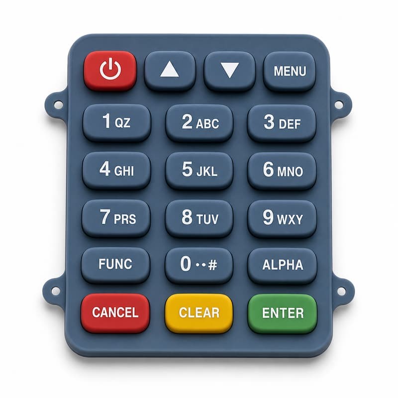
Spacing also interacts with the housing: a keypad that fits too tightly against the bezel transfers pressing force to neighboring keys - the classic cause of "keys that trigger themselves," which we analyze in our 0.1 mm gap clearance study. Operators feel this as ghost inputs, and the fix is a tolerance review, not a software filter.
4. Legends and Color Coding: Designing Glanceable CNC Silicone Keypads
CNC operators read keys with peripheral vision, often in poor light. Two design choices decide whether the layout is glanceable: legend contrast and color coding. White legends on dark keys give the highest contrast under coolant mist and low shop lighting. Color coding should follow a fixed convention - red for stop/emergency, yellow or amber for warning functions, green for start/run - and the convention should not change between machine models, because operators build muscle memory across the fleet.
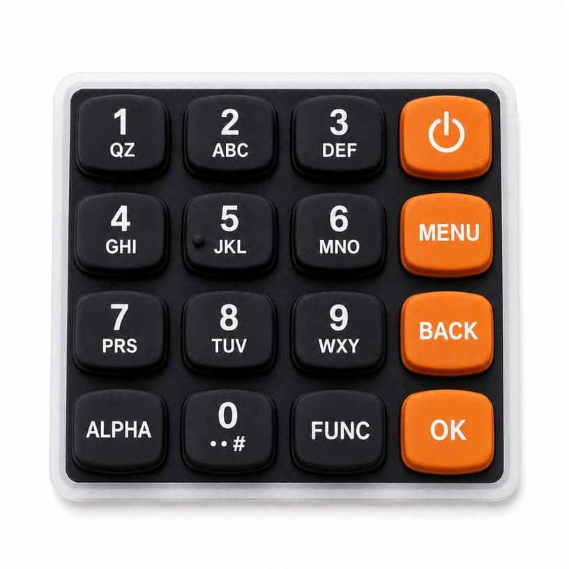
Legend durability is a maintenance cost, not a cosmetic detail. Screen-printed legends on a high-use CNC keypad typically survive a few hundred thousand presses, but aggressive coolants and wiping wear them faster; laser-etching or laser-marked legends penetrate the material and survive the same regime for the life of the keypad. The 3M tape test and a defined rub count should be part of the acceptance criteria. For more on how drawings and tolerances protect these details, see our guide to reading a silicone product drawing.
5. Case Study: Reworking a CNC Pendant Silicone Keypad After Operator Trials
A machine tool builder brought FromRubber a pendant keypad that scored poorly in an operator trial at two customer sites. The keypad had 14 keys at 15 mm pitch, 150 gF actuation, and screen-printed legends. Operators reported mis-presses on the axis jog cluster, no tactile confirmation with work gloves, and the START key legend wearing through in under nine months.
We built three prototype variants: the original layout, a layout with the jog keys at 20 mm pitch, and a third with a raised tactile ring around the axis cluster and laser-etched legends on the six highest-use keys. The trials were unambiguous: the 20 mm pitch version cut adjacent-key mis-presses by roughly 70% in the measured task time, the raised ring eliminated look-down time for the axis cluster, and laser-etched legends showed no measurable wear after the trial period. Actuation force was raised to 240 gF with a higher-snap dome, which operators described as "firm but definite" in the acceptance survey.
Key takeaway: the rework cost less than 10% of a new mold because the changes were made before tooling validation. The same discipline - prototype, trial, then tool - is exactly what our tooling validation guide recommends for every instrument keypad program.
6. A CNC Silicone Keypad Layout Checklist for Control OEMs
Key pitch ≥ 18 mm (20 mm for axis jog and emergency clusters), documented on the drawing
Actuation force 200–280 gF with snap ratio > 1.5, held within ±30 gF across batches
Fixed color convention (red stop / amber warn / green run) unchanged across models
Laser-etched legends on the six highest-use keys; 3M tape + rub test in acceptance
Bezel fit clearance reviewed against tolerance stack to prevent ghost triggers
Operator trial with at least two sites before tooling validation
Every item on this checklist has a measurable effect on the operator experience and on field service cost. If your current keypad layout is fighting your operators, the fix is a specification conversation with a silicone keypad manufacturer who does quality-controlled production - before you cut a new mold.
Sources and Further Reading
The ergonomic figures in this article draw on published industry material: LuphiTouch - Electrical Contact Mechanisms in Silicone Rubber Keypads, Shin-Etsu - Silicone Contact Elements, and Google Patents - silicone keypad prior art. Operator survey findings and engineering estimates reflect FromRubber project records for CNC pendant keypad programs. Related reading: actuation force ranges, gap clearance and ghost triggers, and the Silicone Keypad Technology Sharing series.
About FromRubber - FromRubber manufactures custom silicone keypads for CNC controls, industrial instruments and handheld electronics, with in-house tooling, prototyping and operator-trial support. If your control panel needs an ergonomic review or a reworked keypad layout, our engineers can build prototypes and run the same trials described in this article before you commit to production tooling.