Silicone Keypad for Ultrasonic Thickness Gauge: What Are the Key Design Requirements?
An ultrasonic thickness gauge spends its working life in one hand and against a steel pipe, a hull plate or a storage tank. The other hand holds the probe, the couplant and usually a glove. Every measurement run needs the same keys pressed again and again — menu, up, down, save, enter — and the silicone keypad for ultrasonic thickness gauge projects has to stay findable, pressable and predictable through that routine, for years, without the operator looking at it. When the keys feel different from one press to the next, or slip under a gloved thumb, the measurement workflow stalls in the field, not in the lab.
What Is a Silicone Keypad for Ultrasonic Thickness Gauge?
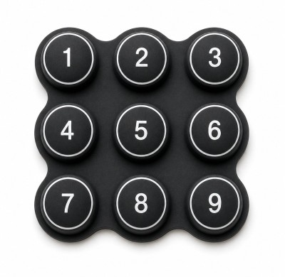
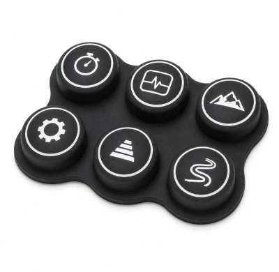
From a manufacturer's point of view, a silicone keypad for a thickness gauge is one molded silicone part that does three jobs at once. The keytops are the visible buttons the operator presses. The membrane — the thin base sheet that connects the keys — carries the layout and usually the sealing skirt around the edge. Under each key, a conductive pill makes the electrical connection to the PCB when the key is pressed. The same shot of silicone produces all three, which is why the pad is a single design rather than an assembly of loose buttons.
NDT equipment demands a different tactile strategy from consumer electronics. A phone button is pressed a few times a day by one person; a gauge key is pressed hundreds of times per inspection, with gloves, in awkward positions, while the operator watches the reading rather than the keyboard. The keypad has to give clear feedback at a force that does not fatigue the thumb over a full inspection day, and it has to return quickly enough for rapid parameter adjustment. Those constraints push the design toward a defined snap action with controlled force — not toward soft, quiet keys.
One thumb, one pad, many functions
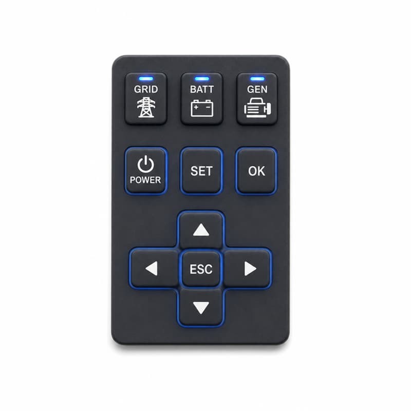
Look at the front of a portable gauge and you usually see between six and twelve keys: a power key, a navigation cluster, a save/enter key and a few function keys. For the keypad maker, the interesting part is that these keys share one membrane, so the web geometry under each key has to be tuned to its own size and role while the whole pad is molded in one shot. That is where consistency between keys is decided — in the mold design, before any material is poured.
Why Do Ultrasonic Thickness Gauges Need Physical Keypads?
Thickness measurement is a field workflow with a strict sequence: couple the probe, read the value, store it, move to the next point. The operator's attention stays on the probe contact and the display, and the keys have to respond to that limited attention. Physical buttons give tactile feedback — the operator confirms the input by feel without looking down. They work with gloves, which capacitive surfaces do not. And they allow quick parameter adjustment, because a gloved thumb can find a raised key faster than it can navigate a flat touch panel.
None of this claims physical keys are universally better than touchscreens. It claims that for a measurement instrument operated with gloved hands, in the field, with the display already carrying the data, a mechanical keypad with defined force and travel is the lower-risk interface.
What Can Non-Slip Silicone Keys Add to a Thickness Gauge?
One documented feature of the Linshang (LSH) ultrasonic thickness gauge family is worth examining closely. The manufacturer describes the LS213 — the international model of the 86213 — as housed in an ABS plastic shell "with non-slip silicone keys" for a comfortable grip and easy operation [5]. The same family covers the 86211 and 86212 models, which are documented for non-destructive thickness testing of metals, plastics, ceramics and glass with a resolution up to 0.001 mm [1][2][3][4].
What does "non-slip silicone keys" actually mean from a keypad engineering perspective? Three things. First, finger positioning: a textured or soft-touch key surface gives the thumb a stable purchase, so the press lands on the intended key even with wet or dirty hands. Second, surface friction: a low-slip top surface reduces the chance of the thumb sliding off a small key during a quick press. Third, grip confidence: if the key area is also the main tactile reference on the instrument body, the operator holds and operates the gauge with the same hand, and the key surface contributes to that grip.
We should not claim more than the documentation says. LSH documents the non-slip silicone key feature; it does not publish actuation force curves or surface roughness values for these keys. From a silicone keypad manufacturer's viewpoint, the documented feature translates into a specification that can be engineered: key-top texture (fine matte, coarse matte or ribbed), compound hardness, and surface finish on the mold cavity. Those choices are exactly what a custom silicone keypad supplier controls.
What Are the Key Design Requirements for a Silicone Keypad for Ultrasonic Thickness Gauge?
The requirements for an NDT keypad collapse into seven engineering areas:
- Tactile feedback — a clear actuation step so the operator feels the input register, even through a glove.
- Non-slip surface — key-top texture and finish that keep the thumb on the key in wet or dirty field conditions.
- Actuation force — high enough to avoid accidental presses, low enough to avoid fatigue over a full inspection day.
- Key travel — enough movement to compress the conductive pill reliably, with controlled overtravel.
- Mechanical durability — the web must survive repeated actuation without tearing or losing return force.
- Electrical reliability — stable contact resistance between the carbon pill and the PCB pads over the life of the pad.
- Housing integration — fit, locating features and sealing against dust and moisture in the field.
These seven areas are one design, not a checklist. The force target and the travel target both live in the same web geometry; the non-slip texture is molded on the same keytop that carries the legend; the sealing skirt shares the membrane with the key area.
How Should Actuation Force Be Optimized for Thickness Gauge Keypads?
Actuation force is the most misunderstood specification in NDT keypad work, because it is quoted as a single number when it should be specified as a curve. The design guides define the force-travel curve by three points: the actuation force F1 where the web collapses, the contact force F2 where the pill touches the PCB pad, and the snap ratio (F1 − F2) / F1, which measures the strength of the tactile step [6].
For a thickness gauge, the optimization targets repeated operation and gloved use. The peak force has to sit in a window: too low, and the weight of a gloved hand resting on the panel triggers accidental activation during a scan; too high, and a full day of measurements wears the thumb out. The tactile threshold — the snap — has to be strong enough to be felt through a glove, and the return force has to be strong enough that the key snaps back before the next press in a rapid sequence.
This is why a gauge keypad should be judged on the measured force-travel curve at a stated temperature, not on a "soft" or "hard" impression. Silicone stiffens in the cold and softens when warm — the material's documented service range is broad, roughly −55 °C to 250 °C [6] — and a gauge is used outdoors, so the force envelope should state the temperature at which it must hold.
The curve, not the number
On our shop floor, every key of a prototype is measured on a load-cell force-travel tester, and the report shows the full curve per key, not a single peak value. Two pads can share the same peak force and feel completely different, because one collapses with a crisp snap and the other slides into contact. The operator reads the snap; the tester reads the curve. We release a keypad design only when the curve matches the target across the whole layout, not when the peak is in range.
How Does Keypad Geometry Affect the Performance of an Ultrasonic Thickness Gauge?
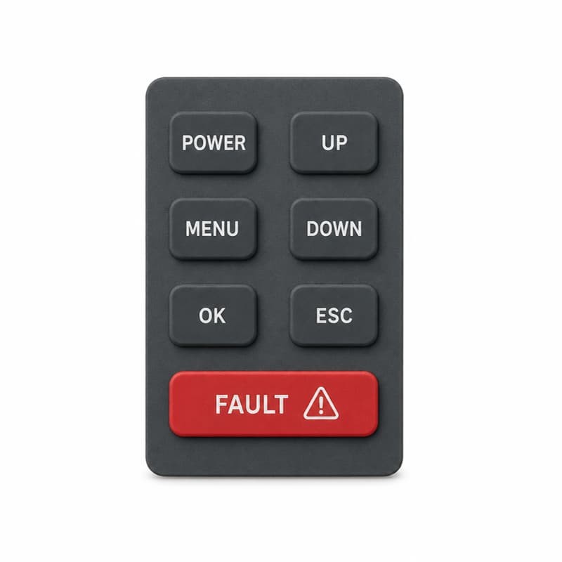
Keypad performance is geometry. The key diameter sets the area the thumb presses and the space available for the web. Key spacing decides whether gloved fingers can target individual keys without hitting neighbors. Button height and the web thickness determine the force-travel curve: a thicker web resists more and returns harder; a thinner one collapses sooner. The membrane between the keys carries the layout and the sealing skirt, and its thickness contributes to the overall flexibility and the pad's seating in the housing.
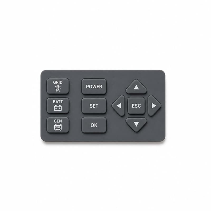
Layout geometry, read from the drawing
Key diameter, pitch, button height and web thickness are all dimensions an OEM can specify and a supplier can measure. When the drawing states them, the prototype is a verification step; when the drawing omits them, the prototype becomes an expensive guessing game.
Housing support and PCB position complete the picture. The pad sits between two rigid parts, and the travel budget has to account for both: if the PCB sits lower or higher than nominal, the pill's contact point moves with it. Tolerance stack-up is the reason a pad that works in one assembled unit can fail in another. The drawing has to state the pad's free height, the compressed height at assembly, and the overtravel available above the contact point, so the whole assembly range works — not just the nominal stack.
How Does a Silicone Keypad Manufacturer Validate a Thickness Gauge Keypad?
Validation for an NDT keypad runs across four domains, and each has its own check:
- Mechanical — dimensional inspection of the pad against the drawing, fit test in the actual housing, force-travel measurement per key, and travel checks at the extremes of the assembly tolerance.
- Electrical — contact test per key, contact resistance measurement at rated force, and switch reliability over repeated cycles.
- Cosmetic — graphics legibility and abrasion, surface finish consistency, flash control, and contamination checks on the pad.
- Assembly — housing fit, PCB alignment, key return after repeated presses, and sealing checks in the assembled instrument.
Each domain is a gate. A pad that passes dimensional checks can still fail electrical contact because the pill sits off-center; a pad with perfect electrical performance can still feel wrong because the snap ratio drifted during curing. The validation report should carry the measured values, not just a pass/fail line.
Why Can a Keypad Prototype Pass Testing but Show Force Variation in Mass Production?
This is the question that separates prototype approval from production readiness, and it deserves a direct answer: prototype approval proves a design can work; it does not prove a process can repeat it. In mass production, six sources of variation act on the force curve.
- Material variation — incoming compound batches differ slightly in viscosity and hardness; the cure state after molding shifts the final durometer.
- Molding variation — shot pressure, temperature and clamp force vary within their process windows and change how the material fills the web cavities.
- Curing variation — time and temperature across the batch affect crosslink density, which changes hardness and return force.
- Cavity variation — a multi-cavity mold produces slightly different parts from each cavity; the force curve should be tracked per cavity.
- Web thickness — the single most sensitive dimension for feel; small tooling wear or flash on the web edge changes the snap.
- Conductive pill placement — pill position and geometry affect contact reliability and effective travel.
That is why production release includes in-process force and resistance sampling, batch records, and dimensional checks — not a one-time prototype sign-off. A keypad design is production-ready when the measured force spread across cavities and batches stays inside the window the operator can feel as consistent.
What Information Should an Ultrasonic Thickness Gauge OEM Provide for Custom Keypad Development?
A thickness gauge OEM that wants one design round instead of five sends this package in the first inquiry:
- CAD files — housing 3D model and 2D drawing, including the keypad opening and any locating features.
- PCB — contact pad positions, heights and tolerances.
- Key layout — key count, positions, sizes, pitch and the function of each key.
- Target force — peak actuation force and snap ratio, plus the temperature range.
- Target travel — key travel and overtravel above the contact point.
- Environmental requirements — temperature range, dust and moisture exposure, cleaning regime.
- Graphics — legends, symbols, colors and any backlit areas.
- Material requirements — any compound constraints, compliance needs, or documented feature expectations such as non-slip key tops.
- Production quantity — annual volume, which decides tooling strategy.
Missing items should be stated as assumptions on the quote. A quote that silently guesses compound, force and tolerance produces the wrong part in the most expensive possible way — after tooling.
How Can a Silicone Keypad Manufacturer Support an Ultrasonic Thickness Gauge Project?
The support sequence follows the engineering dependencies: DFM review of the housing and PCB data before any tooling commitment; tooling design with shrinkage compensation for the chosen compound; prototypes molded from production-intent tooling where possible; engineering validation including force measurement, electrical testing and fit checks in the real housing; a pilot production run that samples force spread across cavities; then mass production with in-process control and inspection. An experienced instrument-keypad shop does not sell "a rubber pad"; it sells the engineering chain that makes the pad repeatable.
FAQ
Why are silicone keys useful on thickness gauges?
Silicone keypads are molded as one continuous part, which gives the gauge a sealed, contamination-resistant front surface with defined tactile feedback — suited to field instruments that are pressed repeatedly with gloved, dirty hands.
What does "non-slip silicone keys" mean?
It is a documented feature of products such as the Linshang LS213 gauge, which the manufacturer describes as housed in an ABS shell with non-slip silicone keys for a comfortable grip [5]. In engineering terms it refers to key-top texture and surface finish that keep the thumb on the key in wet or gloved conditions.
How is keypad force measured?
On a load-cell force-travel tester, which records the force as the key is pressed through its travel. The output is the F1 actuation force, the F2 contact force and the snap ratio — the curve, not a single number [6].
How can glove operation affect keypad design?
Gloves damp the tactile step and change how the press lands. The snap ratio has to be high enough to be felt through the glove, the key spacing has to suit a gloved finger, and the peak force has to sit below the fatigue threshold for repeated gloved presses.
Can silicone keypads be customized for NDT equipment?
Yes. Key layout, force, travel, surface texture, graphics, conductive contacts and the sealing interface are all moldable design parameters. NDT OEMs routinely customize these for their instrument housing and PCB.
How does a manufacturer control key force?
Through web geometry and compound selection at design time, and through process control — material batches, molding parameters, curing conditions and per-cavity sampling — at production time. The measured force curve is the control target.
Conclusion
For an ultrasonic thickness gauge, keypad design must balance tactile feedback, non-slip operation, electrical contact reliability, mechanical durability and manufacturing consistency — and all five are set in the same molded part. The documented non-slip silicone keys of the LSH gauge family show what a mature field instrument specifies; the engineering underneath — web geometry, force curves, pill placement and cavity control — is where a silicone keypad manufacturer earns its place. If you are developing a portable NDT gauge, a housing CAD file, PCB layout and a button plan are usually enough for a silicone rubber keypad manufacturer to begin a DFM review.
This article was written by the molding engineering team at FromRubber, a custom silicone keypad manufacturer in Dongguan, China. We mold instrument keypads for portable NDT and field equipment, and the checks described here are the ones we run on our own shop floor before a pad is released to production.
Related reading
Sources
- [1] Linshang Technology, "86211 Ultrasonic Thickness Gauge". https://lshtec.com/product/86211-ultrasonic-thickness-gauge.html
- [2] Linshang Technology, "86212 Ultrasonic Thickness Gauge". https://www.lshtec.com/product/86212-ultrasonic-thickness-gauge.html
- [3] Linshang Technology, "86213 Ultrasonic Thickness Gauge". https://lshtec.com/product/86213-ultrasonic-thickness-gauge.html
- [4] Linshang Technology, "Ultrasonic Thickness Gauge User Manual — 86211, V2.3". https://images.lshtec.com/user-manual/86211_User_Manual_V2.3.pdf
- [5] Linshang Technology, "LS213 Ultrasonic Thickness Gauge" (non-slip silicone keys). https://www.linshangtech.com/product/ls213-ultrasonic-thickness-gauge.html
- [6] Diamond HMI Ltd, "Rubber Keypad Design Guide". https://www.diamondhmi.co.uk/wp-content/uploads/2020/02/Diamond-HMI-Rubber-Keypad-Design-Guide.pdf
- [7] ASTM International, "Standard Test Method for Rubber Property — Durometer Hardness", ASTM D2240-15(2021). https://www.astm.org/d2240-15r21.html