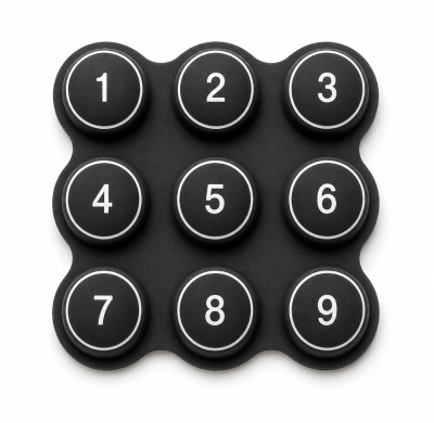
Silicone Button Layout Problems in Wireless Voice Amplifiers
A wireless voice amplifier puts six to ten functions on a panel smaller than a business card, and the keypad has to be operated by a thumb while the device hangs from a belt or sits in a hand. Layout problems on that panel rarely look like layout problems in the field. They arrive as "the volume keeps jumping", "I keep hitting power instead of mute", or "the buttons are too small to find with a glove on".
Most layout problems in wireless voice amplifier silicone buttons come from planning the panel visually before planning it mechanically. Button positions must be fixed by the PCB switch coordinates, then checked for finger access, cap diameter, spacing to the housing opening and web structure between keys. When the layout is drawn from the outside in, the result usually looks balanced and operates badly, and correcting it after the mold is cut costs more than the original design work.
What Are the Most Common Silicone Button Layout Problems in Wireless Voice Amplifiers?
The panel is crowded for a simple reason: the product needs talk, volume up, volume down, mode, power and often mute or a recording function, all within reach of one thumb. Each function wants a large cap and generous spacing, and the housing wants a small window. The compromise is where layout errors enter.
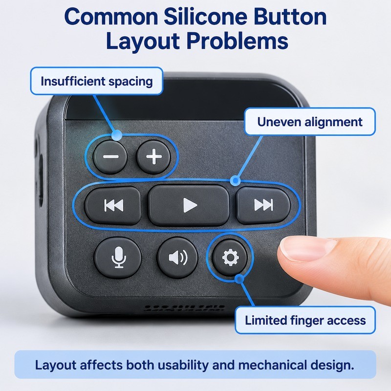
The first problem is spacing. Caps that are close enough to look like a tidy group are also close enough for a thumb to bridge two of them, especially when the device is held at an angle. The user then presses harder to be sure, which increases the chance of hitting the neighbour.
The second is alignment. Rows that are visually even but dimensionally inconsistent produce a panel that looks acceptable in a render and shows a wandering gap in production, because the plastic opening and the silicone caps accumulate tolerance in opposite directions.
Buttons Placed Too Close Together Are Difficult to Operate
The distance between cap edges is what the thumb experiences, not the distance between centres. Two buttons with the same pitch can feel completely different if one has a larger cap. On a panel where the caps are molded as one silicone sheet, the gap between caps is also the web width, so spacing decisions directly change how much one button drags its neighbour.
A practical way to review this before tooling is to print the panel at 1:1, place it in a rough housing or a cardboard mock-up, and operate it with the thumb of the hand that will hold the product. Most spacing complaints appear in that test within a minute, and they are much cheaper to fix on paper.
Uneven Button Positions Make the Control Panel Look Unbalanced
Visual balance is not only an aesthetic issue. When the caps are not evenly spaced, the eye reads the panel as poorly made, and users lose confidence in the product before they press anything. The cause is usually that the layout was adjusted locally to clear an internal component without re-spacing the whole group.
A second cause is the housing. If the plastic opening is molded with a draft angle and the silicone caps are positioned from the PCB, the visible gap between cap and opening changes across the panel. The caps are correct; the window is not.
Small Buttons May Be Difficult to Identify and Press
Cap diameter, cap height and legend size form a single readability problem. A small cap can carry a legible symbol if the legend is printed cleanly and the surface is flat, but it cannot offer much finger contact area. When the same small cap also has to be found by touch, the height difference between keys becomes the only cue the user has.
This is where surface features earn their place. A raised bar, a recessed ring or a small dome on a frequently used key gives the thumb a reference without adding printed graphics. The features have to be molded into the cap, so they belong in the layout discussion rather than in a later decoration step.
How Does Button Layout Affect the Mechanical Performance of a Silicone Keypad?
Layout is usually treated as a two-dimensional drawing. In a silicone keypad it is a three-dimensional structure, because every gap in the drawing becomes a web in the molding, and every web connects two springs.
When caps are placed close together, the web between them is short and stiff, and pressing one cap pulls the other down. When they are far apart, the web is long and flexible, but the sheet becomes harder to mold without distortion and the outer frame grows.
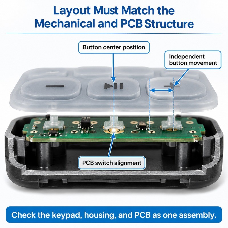
The same drawing also has to satisfy the PCB. The conductive pill under each cap must sit over its switch pad, and the tolerance stack runs from the silicone, through the housing, to the board. A layout that ignores that stack will produce a panel where the centre keys work and the edge keys are marginal.
Insufficient Clearance Can Cause Buttons to Interfere With Each Other
Two caps that do not touch in the drawing can touch in the molding. Silicone flashes at the parting line, the cap side wall has draft, and the sheet can bow slightly after demolding. A gap that looks adequate on a 1:1 print can close in production.
The interference shows up as a pair of keys that feel heavier together than separately, or as a key that returns only when its neighbour is released. Checking it is straightforward: press each key individually and watch the caps around it with a low raking light. A cap that dips by even a small amount is coupled.
Incorrect Button Positioning Can Cause PCB Contact Misalignment
The conductive pill is a small target. If the cap centre is offset from the pad centre, the pill closes the contact on one edge, and the resistance becomes sensitive to how the user presses. A press at the centre may register, a press at the edge may not.
Positional deviation comes from three places: the silicone layout itself, the housing's position relative to the PCB, and the PCB's position relative to the housing. In practice the silicone is blamed first because it is the part that gets remade. Measuring the assembled stack before changing the tool usually shows which of the three actually moved.
Uneven Button Heights Can Create an Inconsistent Pressing Feel
Heights are often set by the housing opening rather than by the finger. A cap that protrudes more is easier to find but can be knocked; a cap that sits flush is protected but harder to locate. Mixing the two across a panel without a reason produces the impression that some keys are worn.
Where a height difference is intentional, it should follow function: the talk key can sit slightly proud because it is pressed most often and needs to be found without looking, while rarely used setup keys can sit lower. The difference then reads as design rather than inconsistency.
What Should Engineers Consider When Planning a Wireless Voice Amplifier Button Layout?
The order of work decides the outcome. Start from the electrical requirement, then the finger, then the housing, and leave the decoration until the mechanics are settled.
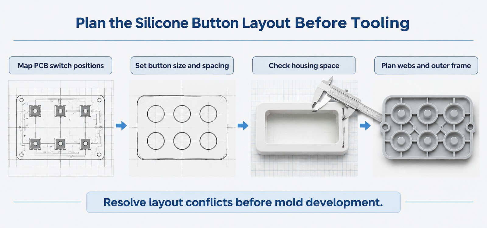
Start With the PCB Switch Positions and Functional Requirements
List the functions, then decide which need to be reachable without looking. On a voice amplifier that usually means talk, volume and mute. Those keys deserve the largest caps and the most generous spacing; mode and power can be smaller and placed at the edge of the group.
Map the switch coordinates before drawing the caps. If the PCB is already fixed, the caps have to follow it, and the layout question becomes how to fit usable caps over those positions. If the PCB can still move, the layout can be designed around the hand first, which is the better sequence.
Balance Button Size, Spacing, and Available Housing Space
Measure the usable front panel, then subtract the frame width the keypad needs to seal and locate. What remains is the area available for caps and webs. A layout that fills that area completely will have no room for the outer frame and will lift at the edges.
Spacing should be set from the finger, not from the drawing grid. A simple test is to place three coins of the intended cap diameter on the print and press them in sequence with a thumb. If the thumb cannot land on one without touching the next, the spacing is too tight regardless of what the dimensions say.
Plan the Supporting Webs and Outer Keypad Structure
The web is the layout's hidden variable. Thin webs give independent keys but weak tear resistance at the corners; thick webs give a robust sheet but couple the keys. The compromise usually sits at a web that is thin in the middle of the span and thicker where it meets the cap and the frame.
The outer frame has to locate the keypad, carry the mounting features and survive demolding. Complex layouts with narrow gaps between caps and a thin frame are difficult to fill and to strip from the mold, and the molding difficulty often shows up as dimensional variation in exactly the keys that had the least space. When the keypad and the housing are toleranced separately, the tolerance classes in ISO 3302-1 give both parties the same vocabulary for moulded rubber dimensions.
| Layout variable | What it governs | If it is too small | If it is too large |
|---|---|---|---|
| Cap diameter | Finger contact area and legend space | Hard to find, easy to press two keys at once | Limits spacing, reduces frame area |
| Edge-to-edge spacing | Independent operation and mis-press risk | Thumb bridges keys, webs couple movement | Panel runs out of room, caps become small |
| Web thickness | Coupling between adjacent keys and tear strength | Keys drag each other, corners tear | Stiff sheet, heavy feel, poor demolding |
| Cap height above panel | Tactile location and protection | Keys hard to find by touch | Keys snag, accidental presses, cap damage |
| Outer frame width | Sealing, location and edge stability | Edge lift, poor seating in the housing | Reduces usable area, raises force at panel edge |
| Pill-to-pad offset | Contact reliability across the cap surface | Contact closes only at the centre | No effect on force, but indicates a stack error |
How Can Custom Silicone Keypad Design Solve Button Layout Problems?
Custom design is not only about making a new shape. It is the ability to adjust individual caps, the web between them and the frame around them as one part, then test the result against the actual PCB and housing.
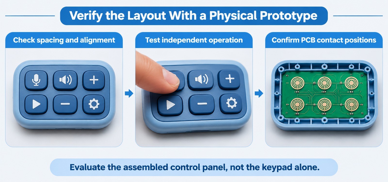
Adjust Individual Button Shapes and Positions
Once the functions are ranked, the layout can become deliberately uneven. The talk key may be wider than the others, the volume pair may be shaped as a rocker-like pair with a visible divide, and the power key may be recessed to prevent accidental shutdown. These differences are all molded into the same sheet, so they cost little once the tool exists.
Tactile differentiation is worth planning at the same time. A raised bar on the talk key, a concave dish on the volume keys and a flat surface on the mode key give the thumb three different references. Users learn them quickly, and the panel becomes operable without looking, which is exactly what a handheld amplifier needs.
Optimize the Keypad Around the PCB and Plastic Housing
The three parts should be reviewed together, on paper and then in a physical sample. The silicone drawing defines cap positions; the PCB defines pad positions; the housing defines the window and the support surface. A change to any one of them moves the others.
Where the housing cannot change, the keypad can often absorb the difference by adjusting cap height or by adding a small locating feature. Where the PCB cannot change, the cap positions are fixed and the layout work moves to spacing and cap size. Knowing which part is frozen early saves a sample round.
Use Prototype Testing to Confirm Layout Usability
Test with the product in the hand, at the angle it will be used, with the thumb that will operate it. Check that each key can be pressed without touching its neighbour, that the contact closes across the usable area of the cap, and that the caps do not rub in the housing window.
It is also worth testing with a glove if the product will be used outdoors in cold weather. A layout that is comfortable with a bare thumb can be unusable with a glove, and the fix is much easier before the tool is cut.
What Information Should OEM Buyers Prepare Before Customizing a Silicone Button Layout?
A layout review moves quickly when the buyer can supply the mechanical context. The list below is what we ask for before quoting a custom keypad layout.
Front panel drawing
The visible window, the frame around it and the position of any display or indicator. This defines the space the keypad must fit.
PCB switch layout
Pad coordinates, pad diameter and switch type, so the cap centres can be placed over the contacts rather than estimated.
Function list and priority
Which keys must be reachable without looking, and which can be secondary. This drives cap size and height.
Installation space
Depth available behind the panel, support surface under the keypad, and how the keypad is retained.
Housing material and colour
Affects the visible gap, the contrast of the caps and the friction between cap and opening.
Legend and surface requirements
Symbols, language, whether the legends are printed or laser etched, and the surface texture of the caps.
Why Work With a Custom Silicone Button Manufacturer During Layout Development?
Layout decisions cross three disciplines, and the manufacturer is the party that sees all three parts in physical form. A supplier who molds keypads every week can tell from a drawing whether the web will couple, whether the frame will demold, and whether the caps will rub in the window, before any tooling is committed.
At FromRubber the layout review happens on the same site as the mold shop and the printing line, so a spacing change can be tested as a sample rather than discussed as a possibility. The custom silicone rubber keypad range covers single-sheet keypads, keypads with conductive pills and backlit constructions, and the keypad product list shows representative panels with different button counts and pitches.
For panels that combine a silicone keypad with a membrane switch layer, the layout has to satisfy both parts at once. The membrane switch keypad construction page shows how the layers stack, and the screen printing page covers legend production for small caps.
A Note on Panels That Are Already Too Tight
When the housing is fixed and the panel is already crowded, layout freedom is limited. In that situation the useful options are usually a height difference between keys, a change of cap shape from round to oval to gain edge-to-edge clearance, or moving a rarely used function to a secondary position. Each is a tooling change, but a small one compared with redesigning the housing.
The article on limited panel space covers the same constraint on a different product, and the button height discussion is relevant when height is used as the differentiating cue.
Frequently Asked Questions
How much space should be left between two silicone buttons?
There is no universal figure. The gap has to allow independent cap movement, enough web for tear strength, and enough clearance that a thumb cannot easily bridge two caps. Review it with a 1:1 print and a thumb, then confirm in a molded sample.
Can the button layout be changed without a new mold?
Only in limited ways, such as changing the legend or the surface texture. Cap position, diameter and spacing are in the cavity, so moving a button requires tooling work. This is why layout review before tooling matters.
Should the talk button be larger than the others?
Usually yes. It is pressed most often and needs to be found without looking. A larger cap with a raised feature also reduces the chance of pressing the neighbouring volume key by mistake.
Why do the edge buttons feel different from the centre buttons?
Because the housing supports them differently and the frame is closer. The wall on an edge button may be partly restrained by the frame, which raises the force. Checking each position in the assembly shows whether the difference is acceptable.
Do printed legends limit how small a button can be?
They do. A symbol needs a minimum stroke width and clear space to stay legible after wear. If the cap is too small for the legend, the layout has to change rather than the print resolution.
Sources and verification notes
- FromRubber technical article: how limited panel space affects silicone button design.
- FromRubber technical article: button height and control panel assembly.
- FromRubber keypad FAQ: silicone keypad questions.
- Standard designations referenced for orientation only, by name: ISO 3302-1 (dimensional tolerances for moulded rubber products), ISO 48-4 (rubber hardness). Confirm the applicable class and edition with your supplier and test house.
- Reference works on control layout and target size are not linked here; the spacing guidance in this article is described in practical terms and should be validated on a physical mock-up for the specific product.
The observations above come from layout reviews on compact audio, instrumentation and handheld control panels. Dimensions are deliberately not fixed, because usable spacing depends on cap size, housing support and how the device is held.
If a panel layout is still at drawing stage, send the front housing drawing and the PCB pad coordinates. We will return a marked-up layout showing where the caps, webs and frame need to move before tooling.
FromRubber, Dongguan Bohao Electronic Technology Co., Ltd.
WhatsApp and WeChat: +86 18676210913. The contact page reaches the same engineering team.