How Does Limited Panel Space Affect Silicone Button Design in Particle Counters?
A particle counter that resolves 0.3 µm still has to be driven by a thumb in a nitrile glove. When the enclosure is already carrying a display, an inlet nozzle, a battery pack and two connectors, the button field is whatever area is left — and that leftover area is where most of the ergonomic damage in a compact instrument gets done.
The trouble usually starts with the order of work. The display is fixed first because it drives the optical stack. The PCB is fixed second because it drives the sensor path and the airflow. The keypad drawing comes last, into the gap that remains, and it is squeezed until it fits. Two tooling rounds later, the same drawing is being blamed for mis-presses in the field, although nothing about the keypad was ever wrong on its own.
Why Is Button Space a Challenge in Particle Counter Design?
The button field on a particle counter is not a design element that can be sized on its own. It is the residue of five other decisions, and every one of them is harder to move than the keypad. A display window needs a bezel and a sealing land. The inlet nozzle needs a straight run to the optical chamber. A battery door needs a hinge. The enclosure wall needs a gasket groove, and the gasket groove needs flat material around it. What is left in the middle is often 30 to 40 percent smaller than the area a designer sketches in the first concept review.

On a handheld instrument the constraint is worse than on a bench unit, because the same face has to be reachable by one hand while the instrument is held. The thumb sweeps an arc, not a grid. A layout that looks tidy in a front elevation can put the two most used keys at the outside of that arc, which is exactly where the thumb has the least control.
There is also a sealing penalty that is easy to forget. If the panel has to meet a defined ingress rating under IEC 60529, the perimeter of the button field becomes a sealing land, and the land cannot carry buttons. On a small panel that single requirement can remove more usable area than the display bezel does.
How Do Displays and Sensors Reduce Available Button Space?
Displays take space in three layers, not one. There is the visible window, the bezel around it, and the flat sealing surface behind the bezel. On a 2.4 inch panel the visible window might be 48 mm wide, but the space actually consumed is closer to 60 mm once the bezel and seal land are counted. Indicator LEDs add a second strip. Connectors add a third, because a sealed connector needs a raised boss and usually a keyed orientation.
Sensor hardware is less obvious but often more expensive in space terms. The inlet path has to stay straight and short, which pushes the optical block toward one side of the enclosure and leaves an asymmetric area for controls. Designers then fill that asymmetry with a button row that follows the housing rather than the hand, and the resulting layout is the one that produces complaints about the "wrong" key being hit.
What Problems Occur When Silicone Buttons Are Too Closely Spaced?
Close spacing does not fail in the drawing. It fails at the point of contact. Four problems show up repeatedly:
- Adjacent activation. A fingertip contact patch on a gloved hand is wider than most engineers assume. When the gap between button edges falls below roughly half the button diameter, the same press can load two domes at once, and the second one may be the one that registers.
- Glove operation. Nitrile and PU-coated gloves reduce tactile resolution and increase the contact area. A layout that is comfortable with a bare finger can become a two-handed operation in a cleanroom glove.
- Poor finger positioning. Without a raised profile or a recessed boundary, the thumb has no edge to locate against, so the user looks down before every press. That defeats the purpose of a tactile keypad.
- Inconsistent interaction. Two operators pressing the same key in different ways produce different actuation results, which is the beginning of a service complaint that cannot be reproduced in the lab.
How Does Limited Space Affect Silicone Button Dimensions and Layout?
Once the available area is fixed, three variables compete: button diameter, gap, and count. Any two can be chosen freely, and the third follows. Most projects try to protect the count, because the function list is owned by marketing or by the application, so diameter and gap get squeezed instead. That is the wrong order, and the reason is mechanical rather than aesthetic.
Why Should Button Size Match the Intended Operation?
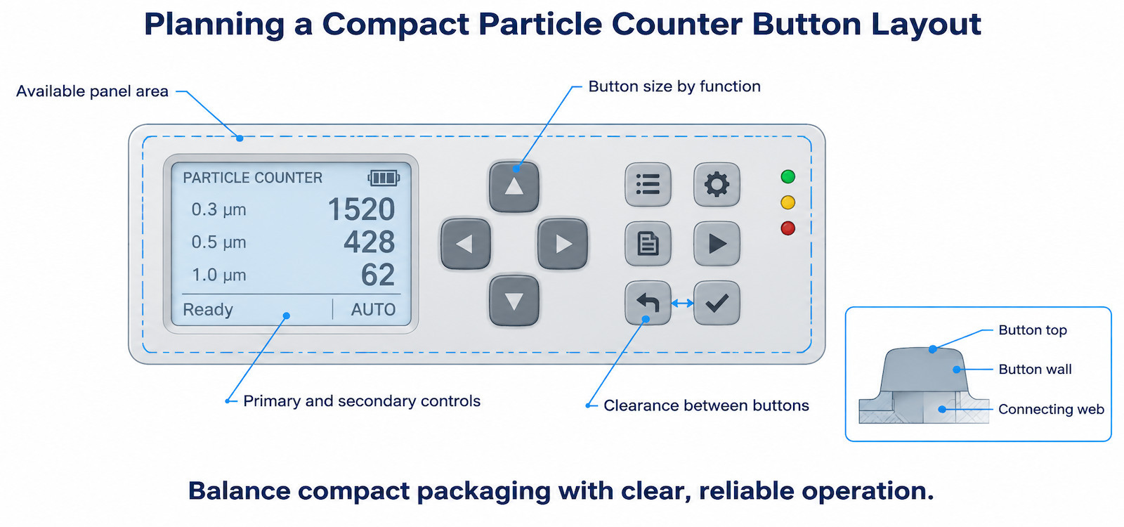
A button's diameter is a statement about how often it will be used. The key that starts a sample run and the key that opens a settings menu do not deserve the same area, and giving them the same area wastes the scarcest resource on the panel. In practice, three tiers work well on instruments of this size: a primary tier of two to four keys at 10 to 12 mm, a secondary tier at 7 to 9 mm, and a setup tier that can be smaller still, provided it is recessed or guarded.
Uniform small buttons are the most common compromise, and they are the one that ages worst. They look consistent in a render, but they remove the only cue a gloved hand has: size difference. A user who cannot feel which key is which will look at the panel, and an instrument that must be looked at during operation is a slower instrument.
How Can Button Spacing Prevent Accidental Activation?
Spacing is usually specified as a single number, and that number is usually wrong because it is applied everywhere. The gap that matters is not the gap between edges; it is the distance between the centres of two domes divided by the stiffness of the web between them. Two keys 3 mm apart behave very differently when the connecting web is 0.4 mm thick and when it is 0.9 mm thick, because the web carries part of the load sideways.
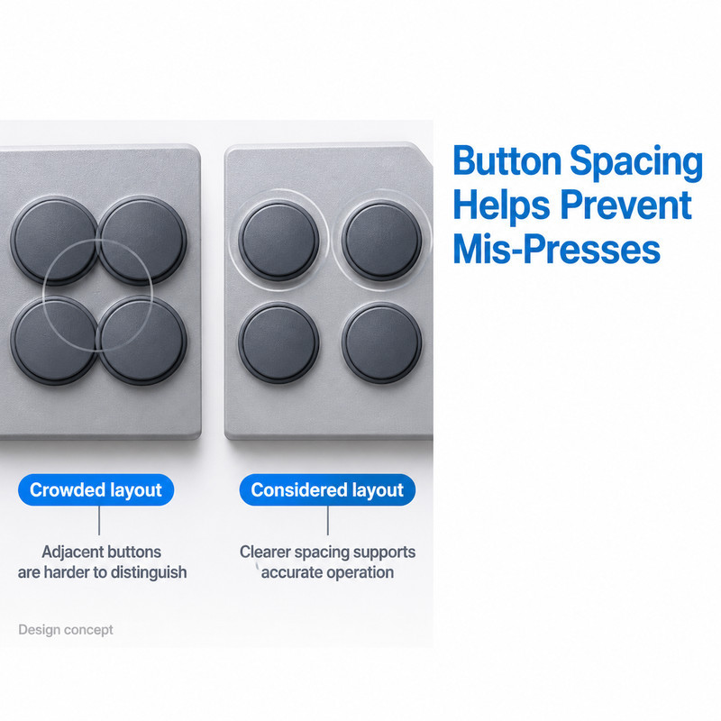
Raised profiles do more for accuracy than extra millimetres do. A crown of 0.6 to 1.0 mm above the surrounding flange gives the thumb an edge to register against, and it separates two adjacent keys even when the edge-to-edge gap is modest. A recessed boundary works the other way round: it keeps the finger inside the intended key instead of letting it slide onto the neighbour.
The evaluation belongs in prototype testing, not in the drawing review. Ask three people to press a sequence of keys with gloves on, then watch where their thumb lands and which key registers. The failure mode is easy to see and hard to predict.
When Should Particle Counter Manufacturers Consider Custom Button Layouts?
Any time the control set is not a standard numeric pad. A particle counter typically needs start, stop, mode, sample time, zero or purge, and a menu pair, and those functions do not map onto a 3×4 grid. Standard layouts also inherit standard spacing, which was chosen for a different housing and a different hand position.
A custom layout is worth the tooling when the panel is asymmetric, when one function is used ten times more often than the others, or when the instrument is operated with gloves. The layout should be drawn together with the enclosure and the PCB rather than after them, because the three constrain each other: a key cannot move without a pad under it, and a pad cannot move without a trace, and a trace cannot move without clearance from the sensor path.
For panels where the housing itself is part of the interface, a moulded custom silicone rubber control panel can carry the button field and the sealing land in one part, which removes a gasket and a tolerance stack at the same time.
How Does Compact Button Geometry Affect Silicone Keypad Manufacturing?
Compact geometry is where a layout that looks reasonable becomes a mold that is difficult to run. The problems are not theoretical; they show up as flash, short shots and dimensional drift between cavities.
Why Can Small Button Structures Create Mold Design Challenges?
Three things happen when buttons shrink. First, cavity spacing shrinks with them, and the steel between cavities becomes thin enough to deflect under injection pressure, which shows up as wall thickness variation from part to part. Second, the parting line has to run somewhere, and on a tightly packed field it runs close to the visible flange, so a normal flash allowance becomes visible flash. Third, material flow into small sections is slower and cools faster, so the last cavities to fill are the ones most likely to be short or under-cured.
Mold layout then feeds back into consistency. A 16-cavity tool with uneven runner balance will produce button fields where one corner feels different from the other, and no amount of assembly inspection will fix it, because the difference is dimensional.
How Should Silicone Button Walls and Connecting Webs Be Designed?
The wall and the web do different jobs and should not be given the same thickness by default. The wall carries the button's height and its return force. The web carries the button's position and part of its neighbouring load. A wall that is too thin loses height under repeated pressing. A web that is too thin tears at the transition or lets the button tilt. A web that is too thick links the keys mechanically, so pressing one lifts its neighbour slightly and changes the feel of the whole row.
What matters more than either dimension is the transition between them. A sharp inside corner at the wall-to-web junction concentrates stress, and that is where a tear starts after a few hundred thousand cycles. A generous radius costs almost nothing in tooling and removes the stress riser.
How Can Manufacturers Balance Compact Layouts With Reliable Button Performance?
Compact and reliable are not opposites, but they are paid for in different places. A tight layout can work well if the force and travel are tuned to the geometry, and it will work badly if the design assumes that a harder compound will solve a stiffness problem created by the web.
How Should Button Travel and Actuation Force Be Evaluated?
Travel is the distance the crown moves before the contact closes. On a small instrument key it is usually in the region of 0.3 to 0.8 mm, and the useful part of that range depends on how much the enclosure allows the keypad to be preloaded. Too little travel and the user cannot tell whether the press registered. Too much and the key feels vague, and the dome may not recover cleanly.
Actuation force is the other half. A force that is comfortable bare-handed can be tiring through a glove, and a force that is crisp through a glove can be too heavy for repeated use. The productive way to evaluate it is to measure the whole force-deflection curve on an assembled sample, not a single peak value, because the shape of the curve is what the user feels. Hardness changes the curve, but geometry changes it more, which is why raising hardness is usually the wrong first response to a heavy-feeling key.
Why Is Prototype Testing Important Before Mass Production?
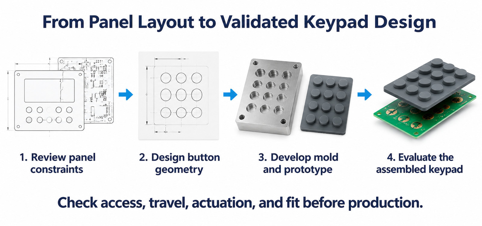
Because most of the failure modes in a compact keypad are assembly-dependent. A key that feels correct on a bare keypad can bind once the enclosure preloads it, and a key that passes a bench press test can mis-register once a gloved thumb approaches at an angle. Prototype evaluation should cover four things: reach and spacing with the intended hand protection, accidental activation across adjacent pairs, tactile response after repeated pressing, and fit against the PCB and switch interface.
A single prototype round is usually enough to expose the layout errors. The dimensional errors that come from the mold are a separate question and belong to the first article inspection.
What Should You Prepare Before Requesting Custom Silicone Buttons?
Which Design Details Help Manufacturers Evaluate Your Project?
A toolmaker can work from a sketch, but the review is faster and more accurate with six items:
- Panel dimensions and the area actually available for buttons, including the seal land.
- Button count, diameter, height above the flange, and edge-to-edge spacing.
- Which functions are used most often, and whether the instrument is operated with gloves.
- Required hardness and surface finish, and whether the legends need to be legible at an angle.
- PCB pad positions, dome or switch type, and the travel the switch allows.
- Cleaning and operating conditions, including any ingress rating the panel has to meet.
How Can a Custom Silicone Keypad Manufacturer Support Development?
The useful contribution at this stage is not a quote; it is a review of whether the layout can be moulded within the tolerance the design needs. That review looks at cavity spacing, web thickness, transition radii and runner balance, and it usually returns two or three options rather than a single answer, because the trade-offs are real.
FromRubber runs 32 compression moulding machines across two plants and an in-house tool room with seven CNC machines, which means the mold review and the sample run are handled by the same team. The silicone keypad design and technical support page describes how that review is usually sequenced, starting from the panel drawing rather than from a finished 3D model.
For projects where the housing is plastic and the keypad is a separate elastomer part, it is worth reading the comparison between P+R keypads and full silicone rubber keypads before the layout is frozen, because the two constructions behave differently at the panel edge.
Questions Instrument Designers Ask Before Tooling
How much gap should there be between two silicone buttons?
There is no single number, because the gap interacts with diameter, dome stiffness and web thickness. As a working starting point for a gloved hand, keep the edge-to-edge gap at no less than about half the button diameter, then confirm it on a prototype with the intended glove. The reasoning behind that ratio is set out in the article on button spacing on patient monitoring keypads, where the same constraint applies.
Can we keep the existing PCB and change only the keypad?
Yes, provided the pad positions and the switch travel stay the same. The keypad can be re-laid out around existing pads, but the dome height has to match the gap between the keypad and the board, and that gap is set by the enclosure.
Where the First Millimetre Should Go
Panel space is fixed early and paid for late. The designs that avoid trouble are not the ones with the cleverest button arrangement; they are the ones where the button field was drawn while the display bezel and the seal land were still negotiable.
The failure that reaches the customer is rarely a drawing error. It is a stack-up error, a flash allowance, or a web specified as one number across keys that do not need the same stiffness. Reviewing the layout as a mechanical system, rather than as a set of circles, is what keeps a compact panel usable.
Sources and notes. Ingress protection ratings referred to in this article are defined in IEC 60529:1989 with amendments 1:1999 and 2:2013, Degrees of protection provided by enclosures (IP Code). Ergonomic criteria for physical input devices are described in ISO 9241-410:2008. Dimensional ranges quoted here are typical working values for handheld instruments, not measurements from a specific project; final dimensions are set by the enclosure drawing, the switch specification and prototype evaluation.
FromRubber, Dongguan Bohao Electronic Technology: custom silicone keypads and moulded silicone buttons. If you are working through a compact panel layout, send the panel drawing and the key list and we will review the geometry before tooling. WhatsApp and WeChat: +86 18676210913.
Published by the FromRubber keypad engineering team.