Digital Level Silicone Keypad Dome Height Tolerance and Inconsistent Button Response
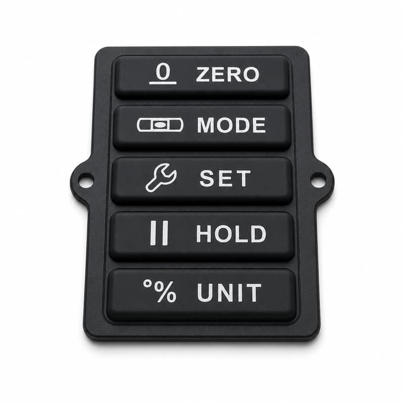
The MODE key on an assembled batch of digital levels wants a firm push, the HOLD key beside it trips on a light touch, and both passed the same drawing. The usual cause is digital level silicone keypad dome height tolerance, the dimension each rubber dome holds before its carbon pill reaches the pads on the customer's board.
Operators report feel rather than tolerances: this key is stiff, that one is soft, ZERO fires early, the panel changed after the last batch. By then the units are assembled and only the silicone keypad remains measurable.
What follows is a work sequence. Define the dimension, measure in a fixed order, decide which readings point at a real problem, then work back through geometry, hardness and housing compression to the feel an operator notices.
Digital Level Silicone Keypad Dome Height Tolerance Starts With a Reference Plane
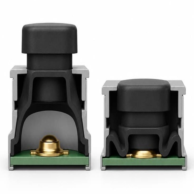
A silicone keypad is not a flat sheet with bumps on it. A base frame carries the panel, a thin web spans the openings, each dome rises off that web, and a conductive carbon pill sits under the dome apex, facing the pads on the customer's board. Press a keytop and the wall leans, the web stretches, the pill travels down, then the shell gives way at its buckling point and snaps through.
What dome height actually measures
Dome height is the vertical distance from a stated reference plane to a stated point on the dome or keytop. Overall height runs from the base seating face to the tallest keytop, keytop height measures one button, and dome height measures to the apex before keytop and coating count. A drawing that names a key height without the reference plane, the measurement point and the stylus force is not a specification, and two people can measure the same part, both be right, and disagree by 0.1 mm.
Silicone is soft, so touching it changes the reading. A gauge landing with 30 grams of stylus force sinks into a 45 Shore A keytop by an amount that shows on the display, while an optical system reading the same part without contact returns something different. The datum has the same weakness: a flash ridge under the base seating face lifts the whole keypad and makes every dome read 0.05 mm tall.
Reading a five key panel as one mechanical system
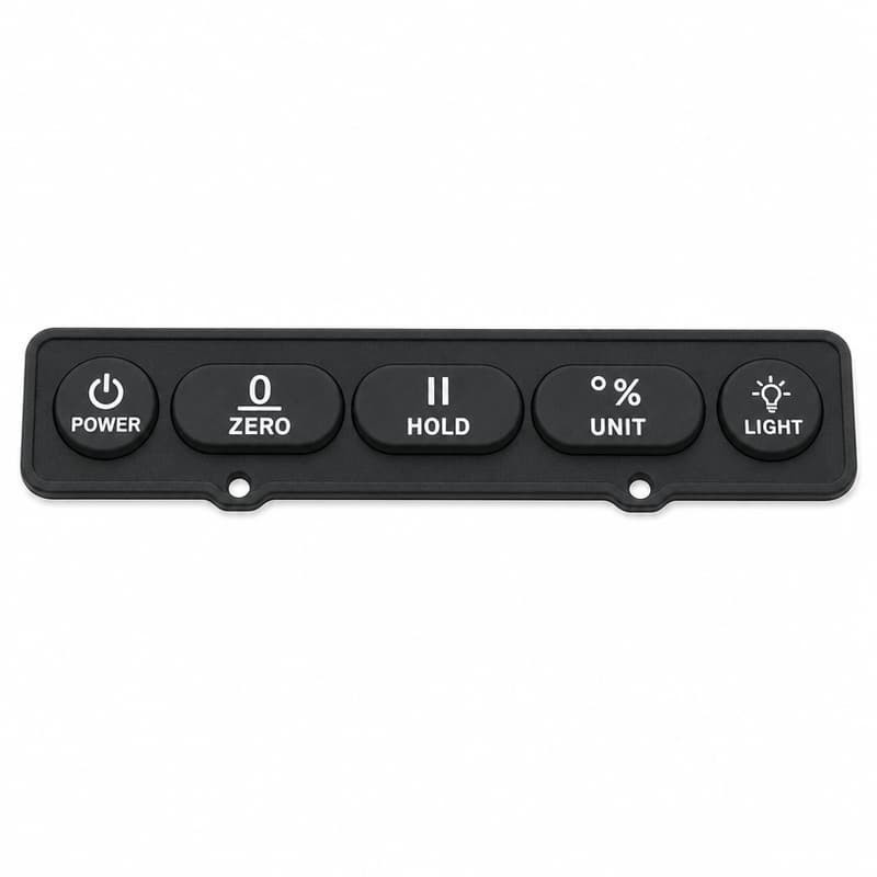
A five key layout such as POWER, ZERO, HOLD, UNIT and LIGHT shares one base frame, one web pattern and one seating plane. The base is molded in a single shot, so a tilt in it moves the reference plane for the whole panel. A web that runs thick between two keys stiffens both, and a base that leans near the mounting posts shows up worst on the key furthest from them.
Dimensional tolerance and functional tolerance are not the same thing
A keypad can sit inside every dimensional band on the drawing and still feel uneven. Dimensional tolerance controls shape: dome height, wall thickness, web thickness, pill recess depth. Functional tolerance controls behavior: the force band in which the switch must close, the travel at which contact happens, the snap the operator feels, and the return force after release. Sign off a program on shape alone and the line receives a part with no promise attached.
How Digital Level Silicone Keypad Dome Height Tolerance Changes Button Response
Once the dome is closed between a board and a housing, its free shape stops mattering. What matters is where the installed dome sits on its own force curve, set by the dome height as molded, the distance from the seating plane to the pads, and how far the housing presses the keypad down.
Installed height, not molded height, sets the starting point
A dome molded 0.10 mm tall does not simply add 0.10 mm of travel. It reaches the board already preloaded, so part of its deflection is spent before anyone touches the key, while a dome molded short runs with a gap between pill and pad that the operator has to close first. The same keypad can feel crisp in a shallow housing and vague in a deep one.
What the force curve does through the press
Plot force against displacement on one key and the curve has landmarks. Force climbs as the wall loads, peaks just before the shell buckles, then drops as the dome snaps through, after which it flattens into a plateau where extra travel costs almost nothing. Contact between pill and pads happens somewhere on that falling or flat region, and where it lands depends on geometry rather than on the keytop shape.
| Stage of the press | Curve behavior | What dome height changes | Bad reading |
|---|---|---|---|
| Pre-snap rise | Force climbs as the wall leans | A tall dome starts higher on the slope, so peak force comes sooner | Two keys on one panel peak 40 grams apart |
| Snap peak and drop | Maximum force, then a fall as the shell passes through | Height shifts where the peak sits in travel and how much drop survives preload | A broad flat peak, or a snap ratio near 1.05 |
| Contact plateau | Nearly flat force while the pill touches the pads | Contact lands earlier or later in travel, following the height error | Closure only at the end of travel, or never |
| Overtravel | Force climbs steeply on the base | A tall dome bottoms sooner, leaving less travel | The key stops hard right after closure |
Snap ratio and contact timing
The usual figure of merit is the snap ratio, the force at the snap peak divided by the force where the switch is asked to close. A crisp small pushbutton often lands between roughly 1.4 and 1.6, while a key near 1.1 has no snap left to feel. Dome height moves both halves of that fraction, because it shifts where in travel the pill meets the pads and how much wall angle is left at the peak. The interaction is set out in this discussion of force, travel and snap ratio in custom keypad tactile feel.
Contact timing follows the same geometry, because switching happens on the underside. The governing dimension is the gap between pill and pads: dome height minus web deflection at the press minus pill recess depth. Two keypads with identical keytop heights and different web thicknesses close the circuit at different points in travel.
Same keytop, different dome, different response
Two buttons in the same housing can share a keytop height and still behave differently, because the dome underneath stores the snap. One stands tall with a steep wall; the other was molded short and now sits partly collapsed under the front panel, having spent part of its travel on preload. What reaches the operator from the short dome is a damped push with a weak return, and the difference comes from cavity position or a housing that pulls the base down unevenly.
Why Digital Level Silicone Keypad Dome Height Tolerance Drifts in the Mold
Cavity to cavity is the first suspect
A twelve cavity tool is twelve small molding systems sharing one press, and center cavities sit in a hotter region than the edge cavities, so they fill and cure slightly differently. If the inserts were machined on separate setups, the difference is built in before the first shot, and 0.03 mm on an insert becomes 0.03 mm on every dome from that cavity for the life of the tool.
Silicone shrinkage is real, and it is not uniform
Molded silicone shrinks as it cures and cools, and how much depends on the compound, the cure temperature and the section thickness. A thin dome wall and a thick base frame do not shrink equally in one cycle, so a cavity cut to nominal dimensions does not produce a nominal part. Toolmakers compensate by scaling the cavity, and that scaling has to be proven against measured parts, as covered in this note on how silicone shrinkage affects molded dimensions. ISO 3302-1 classifies molded rubber dimensional tolerances into classes, so the drawing should name the class.
Compression molding variables that move height
Material weight per shot, mold temperature, cure time, closing pressure and charge placement all affect how far the compound flows before it crosslinks. An undercharged shot leaves short filled webs and thin spots around the pills, while an overcharged shot raises flash thickness and changes the effective seating plane even when the dome is fine.
The tall dome and the short dome over the same board
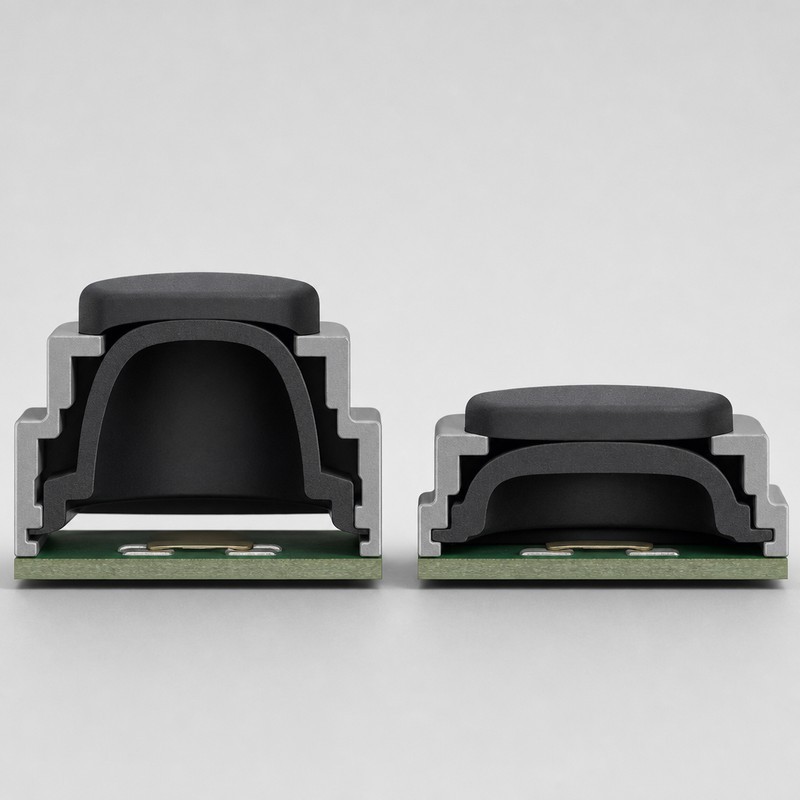
Set a tall dome and a short dome over the same board pads and the difference shows in section. The tall dome travels further before the pill reaches the pad, and its wall is steeper relative to the load, so it builds force quickly and returns a strong snap. The short dome starts closer to the pad, sometimes with the pill nearly touching once the housing closes.
Post-cure and the wait before measuring
Dimensions keep moving after the part leaves the press. Post-curing drives off volatiles and completes the crosslink, and the hours after demolding are when a silicone part is least settled, so the same dome measured an hour out of the press and a day later gives different readings at the same temperature. ISO 815-1 describes how a rubber test piece behaves after being held compressed, and a dome living under housing preload is tested that way, slowly, so the snap weakens long after the dimensional records were signed.
Measure the installed stack before blaming the part
When a batch feels wrong, the fastest way to decide whether the keypad or the assembly owns the problem is to measure both states. Log dome heights on the free part, then installed heights with the keypad seated in the customer's housing at production torque. Consistent free heights with inconsistent installed heights point at mounting compression, a housing face that is not flat, or a board supported unevenly.
Setting the Tolerance That Decides Button Feel
Start from the performance you need, then size the band
Before any dome height number is chosen, decide what the key has to do: the target force at the snap, the range an operator holding the instrument in one hand will accept, the travel at which the circuit should close, the overtravel the housing can absorb, the expected cycle life, and the temperatures it will see. On a handheld instrument the band is narrow, because the same thumb holds the body and presses the key. How actuation force is set for instrument keypads works through that reasoning.
Control the dimensions that touch the function
A drawing with one height callout leaves the numbers that decide feel to the mold shop's judgment. The dimensions worth controlling are dome height with its reference plane, keytop height, dome wall thickness, web thickness, pill recess depth, pill thickness, seating face flatness, and the installed gap between base and board pads. Seating face flatness is the quiet one: a base frame that bows 0.08 mm across the panel moves installed dome height by roughly its own warp at every key.
Stack up the whole interface
Dome height cannot be validated on silicone alone. The stack that decides the installed condition includes keypad base height, board thickness, housing height under the front panel, the compression the mounting method applies, and the clearance above the keytops. That range is often two or three times wider than the dome height band, and when it is, tightening the silicone tolerance is not the fix. Custom silicone keypad manufacturing tolerance becomes an assembly question at that point.
Measuring Dome Height and Button Response in Practice
Dimensional inspection first
Height measurement needs a flat datum, a defined stylus force and a fixed temperature. A digital height gauge on a granite plate covers dome height and keytop height when the stylus force is low and recorded. An optical or vision system measures keytop dimensions, web thickness and pill position without touching the part. A coordinate measuring machine earns its time on new tooling.
Force displacement testing
The measurement that answers the feel question is a full curve, not a single force number. A motorized press with a load cell, driven at a fixed speed, records the press and the release, and speed matters because silicone is viscoelastic and a faster press reads a higher peak. Compare force at the snap peak, force at contact, travel at contact, the return curve, and the spread across all keys on one panel.
Electrical switching verification
Electrical checks belong on the intended board. Testing closure on a bare fixture with flat pads confirms the pill works, but not the gap in the real assembly, where the board may be thinner or the support pattern different. Log the travel at which each key closes, press off axis as well as on center, and watch for keys that close only when pressed dead center.
First article, then a sampling plan that means something
First article inspection is where the drawing and the part meet, and it should cover dimension, force curve and electrical closure in one pass, with the results kept as the reference for the life of the tool. Sampling holds the process afterwards: dimensions at every startup and after any tool or material change, measured across cavities rather than at one convenient position. At FromRubber those records stay traceable to cavity and batch.
What a bad force curve looks like
Four patterns cover most failures. A shallow or missing drop means the dome is already partly collapsed at rest, and the key feels dead. A double bump before the main peak means the pill meets the board before the snap, giving an early electrical trigger with no tactile confirmation. A curve that climbs again after the drop means the dome is bottoming out and the pill is being forced into the pads, which wears the conductive layer. A return curve well below the press curve overlaps with improving tactile response and slow rebound in silicone keypads.
Mistakes That Leave a Digital Level Silicone Keypad with Inconsistent Button Response
Specifying dome height with no reference plane
The most expensive line missing from a keypad drawing is the datum. Without it, a supplier measures from the seating face, the customer measures from the keytop, and both sets of numbers meet in a review where nobody is wrong.
Changing hardness without revisiting the geometry
Switching a compound from 60 Shore A to 40 Shore A to soften a stiff key also changes snap ratio, return force and the point of contact, because force in a dome comes from stiffness and geometry together. Anyone weighing that trade should read choosing between 40 Shore A and 60 Shore A silicone first, then re-run the force curve, since durometer on a finished domed section is not the same as durometer on a flat slab measured to ASTM D2240.
Assuming the housing is innocent, then judging on appearance
A panel that feels even on the bench can feel uneven in the instrument once the front panel presses the base against the board, and that pressure is rarely uniform across a rectangular part. Standoffs at the corners load the corners first, and the key in the middle of the layout goes soft. Sampling one key makes that worse, since cavity to cavity and position within the part are the variations that matter, and a careful visual check touches neither force nor closure.
Design Checklist for Digital Level Silicone Keypads
The list below decides whether a digital level keypad feels the same on unit one and unit ten thousand.
| Design area | What should be verified |
|---|---|
| Dome height | Nominal, reference plane, stylus force and allowable band on the drawing |
| Dome geometry | Wall thickness, web thickness and dome profile, not only the outline |
| Carbon pill | Position, thickness, recess depth and contact geometry on the finished part |
| Key travel | Enough movement before the electrical contact point and after it |
| Board distance | Installed gap from the stack, not copied from an earlier project |
| Housing clearance | No unintended preload, no keytop interference, flat contact at the panel |
| Material hardness | One specified compound and hardness, with batch records per shot |
| Mold precision | Cavity to cavity consistency proven at qualification and after repair |
| Functional testing | Force curve and electrical closure recorded per batch |
| Assembly validation | Keys tested in the final enclosure at production torque |
What to Send With a Custom Silicone Keypad Inquiry
The documents that make an evaluation possible
A 2D drawing with the dome height requirement and its reference plane, a 3D model if one exists, the key travel and overtravel the design allows, the actuation force band that suits the operator, the carbon pill type and thickness if it is already chosen, the pad layout on the board that the pills must meet, housing dimensions including the space above the keytops, and the expected cycle count.
Why the interface has to be reviewed together
Dome height cannot be evaluated apart from the position of the board pads, the clearance under the front panel and the tactile result the operator is supposed to get. A drawing that arrives without the board and the housing will be evaluated against guesses. The review that matters happens before tooling, when changing a dome profile or a pill recess costs drawing hours instead of a re-cut insert.
Feel, from first principles
How force, travel and snap ratio combine into the push an operator feels: force, travel and snap ratio in custom keypad tactile feel.
Choosing a hardness
What moves when a program switches compound: choosing between 40 Shore A and 60 Shore A silicone, and why the dome geometry has to be revisited with it.
Force bands for instruments
How a target band is chosen for a handheld panel: how actuation force is set for instrument keypads.
Questions Engineers Ask Before Tooling
Can we keep the same dome height and use a softer compound to lighten the keys?
It will lighten the press, and it will also lower the snap and move the point of contact, because force in a dome is a product of stiffness and geometry. Often the better move is to keep the compound and adjust dome height or wall thickness, which changes force without moving the material away from what the rest of the program validated.
Our keypads measure within tolerance, but assembled units feel uneven. Where do we look first?
At the installed condition. Measure dome heights on the free part, then measure installed height with the base seated in the housing at production torque. If the free part is consistent and the installed part is not, the variation is coming from mounting compression, a housing face that is not flat, or a board sitting at different heights across the panel.
How much dome height variation is acceptable?
Only the force curve can answer that for a given design. Measure the force band the operator accepts, measure how much dome height change moves a key out of that band, and set the drawing band from that. A keypad with a soft snap and a narrow force window needs a tighter dome height band than one with a strong, forgiving snap.
Final takeaway
Dome height tolerance is a mechanical dimension with an electrical consequence, which is why it causes so much friction between drawings and hands. A keypad can sit inside every dimensional band on its drawing and still deliver a row of keys that respond at different forces and feel different from the previous batch. Defining the dimension against a named reference plane, measuring it under a stated force, and tying it to a functional band taken from force displacement data on the real assembly is the whole method. FromRubber reviews keypad drawings together with the board pad layout and the housing envelope before tooling, because on a digital level the dome, the pill, the board and the panel stop being separate parts the moment the enclosure closes.
Sources and further reading
- Standard Test Method for Rubber Property, Durometer Hardness, ASTM D2240, https://store.astm.org/d2240-15r21.html
- Rubber, vulcanized or thermoplastic, Determination of compression set, Part 1, ISO 815-1:2019, https://www.iso.org/standard/74943.html
- Rubber, Tolerances for products, Part 1, Dimensional tolerances, ISO 3302-1, https://www.iso.org/standard/62492.html