Digital Inclinometer Silicone Keypad Carbon Contact Wear After Repeated Button Pressing
A ZERO key that needs two or three presses before the reading settles is the classic sign of digital inclinometer silicone keypad carbon contact wear after repeated button pressing. The firmware is unchanged and the unit still passes its calibration check, yet the switch that sets the reference no longer closes on the first press.
Units like this come back with a guess attached, usually that the board is failing. Turn the keypad over under a bench microscope and the answer is often visible: one or two pills carry a polished, flattened face where carbon has been rubbed across the customer's pads for tens of thousands of strokes.
This article stays on that interface: the pill, the silicone body driving it, and the pad pattern on the board it closes. What matters is what a keypad molder can hold in tolerance and what the instrument maker has to specify early.
A key that ignores input gets blamed on the board
A digital inclinometer keypad drives a short list of functions: power, unit switching between degrees and percent slope, ZERO or reference calibration, HOLD, angle mode selection, and record or reset. Each closure is a momentary contact across two traces on the customer's board, and also a compression cycle with a sideways component.
Intermittent response is misread because it appears at the worst moment. An installer presses ZERO, sees nothing change, presses again, and the reference is now set twice, while a technician swaps the battery or reflashes the firmware.
Digital inclinometer silicone keypad carbon contact wear after repeated button pressing starts where three surfaces meet
Three parts share the switching interface, and two companies make them: the silicone body that supplies force and return, the pill where current enters and leaves, and the pad pattern on the board.
The silicone body supplies force and return
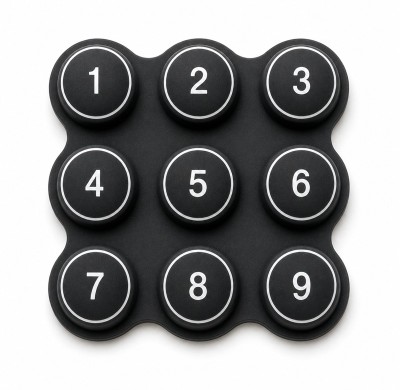
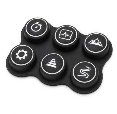
A keypad is one molded rubber part: caps, a thin web tying them together, and a dome or web that bends when the cap is pushed and springs back when the finger lifts. That springback is the whole return mechanism, so the force curve comes from hardness, web thickness, dome height, and cap wall structure.
The carbon pill bridges the pads
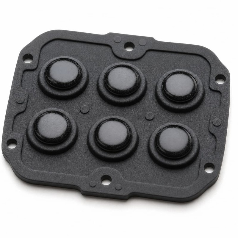
Under each button sits a small disk of silicone loaded with carbon filler, molded so its face stands proud of the surrounding rubber. It has to touch two adjacent pads at once somewhere in the stroke, and its thickness finishes the gap that the rest of the stack defines.
Nickel pills, gold-plated pills, and conductive printing are the alternatives, and each shifts the resistance level, the force needed, and the way the face ages. Settling carbon pill versus nickel pill contacts before tooling costs less than settling it after.

The customer's pad pattern completes the pair
On the board, pad size, the gap between the bridged traces, surface finish, flatness, and cleanliness decide how much of the pill face touches metal, and no universal pad pattern applies across instruments.
Why a compact inclinometer works its keypad harder
The application sets the wear rate as much as the design does. Three things about handheld angle instruments load the contact harder than a bench instrument would.
ZERO and calibration keys take the traffic
Setting a reference is not a one-time event. Users zero the instrument on a known surface, re-zero after moving to another face, switch to percent slope, and press HOLD while writing a number down. The ZERO key takes several presses for every press of any other key.
Small housings squeeze the tolerances
A palm-sized body leaves little room: short travel, the board close to the keypad, small pills because the buttons are small, and a housing opening that partly controls where the press lands. An off-center press then produces more lateral movement.
Site conditions add their own load
Not every inclinometer lives outdoors, and it is wrong to assume all of them do. Instruments used for machine installation, construction layout, and workshop alignment pick up dust, moisture, and solvent cleaning a laboratory unit never sees, and grit on the pads acts as a third body between carbon and metal.
From a press stroke to a polished pill: digital inclinometer silicone keypad carbon contact wear after repeated button pressing
Nothing dramatic happens in one press. The change accumulates, and it accumulates unevenly because the press is never perfectly axial.
Each press is a compression cycle with a scrub inside it
When the cap goes down, the web deforms, the pill approaches the board, and contact closes before the end of travel. Users press off center, toward the upper edge or the thumb side of the key, and that offset becomes a small lateral slide of the pill face. Repeat it a few hundred thousand times and a wear track forms around the perimeter while the middle of the pill still looks new.
Film, not friction, explains the sudden cases
Dark smeared deposits on the pill face or the pads are not abrasive wear. Silicone plasticizer can migrate to the surface, flux residue can sit on the board, and skin oil transfers through the cap gap. Clean the film off and the reading drops back, while abrasive wear never returns to its original value.
A worn pill does not fail the same way in every unit
Formulation, contact pressure, humidity, and the board beneath the pill all shift the picture, so one mechanism is never inevitable. One repeatable pattern is edge thinning, where the pill perimeter loses material faster than the face because molding left that edge thinner, and a case where edge thinning caused conductive failures shows how fast that becomes a field return.
What the change looks like from below
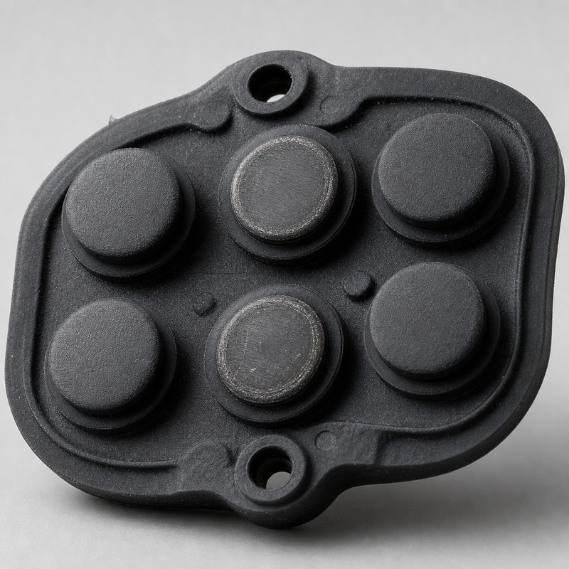
At 20x to 40x, a used pill shows one of four things: an even, dull grey face; a bright polished ring near the perimeter; a dark smeared film that wipes off; or craters where filler has been pulled out of the compound.
Field symptoms and what each one points at
Symptoms are easy to collect and easy to misread. Ask what a symptom would look like if the cause were the board, the assembly, or the pill, then build a check that separates them.
A key that needs several presses, or that misses during a burst
Rising contact resistance is the usual reason a key registers only on a firmer press: the pill reaches the pads, it just does not make enough metallic contact on a light press to pull the input low. A key that misses only during fast bursts is more likely a travel or alignment problem.
Rising resistance and what it does downstream
Contact resistance is constriction resistance plus film resistance, and the standard method for measuring it on a static contact pair is described in ASTM B539. A key reading a few hundred ohms instead of a few tens has lost contact area or grown a film, which is where contact resistance fluctuation reaches measurement accuracy.
One key wearing faster than its neighbors
Compare the keys that get the most traffic, then compare their pill dimensions and their position over the pads. If the fastest-wearing key sits over a pad pair offset by a fraction of a millimeter, wear follows the overlap rather than the usage count.
Failures after storage or a season in the field
A unit that sat in a humid warehouse may show the same intermittent behavior with almost no cycles on it. Humidity, dust, cleaning chemicals, temperature swings, and hand oils all act on the interface.
Wear or contamination: two problems that look alike
Mechanical wear removes material: the face flattens, contact area shrinks, resistance climbs, and the change does not reverse. Contamination adds material: a dark film of plasticizer, flux residue, or skin oil moves the reading press to press, and cleaning restores it. Cleaning answers the second case only.
Design choices that set the wear rate
Five keypad-side variables account for most of the difference between a contact that drifts slowly and one that fails early, and none can be set without knowing the applied force and the pad pattern on the board.
Filler loading and particle distribution
A conductive pill is a silicone compound loaded with carbon filler. Loading sets bulk resistivity and surface hardness; dispersion decides whether resistance is even across the face. Two batches from the same nominal compound can measure differently when the filler is unevenly distributed, which is one reason conductive pill resistance drifts between production batches while every dimensional check passes.
Pill diameter and thickness
Diameter sets contact area; thickness sets where in the travel the contact closes. A larger pill lowers resistance but can crowd the gap between traces; a thicker pill closes sooner and preloads the contact, raising the resting force on the web.
Silicone hardness and the force budget
Durometer, measured to the method described in ASTM D2240, is the first property to freeze. A keypad at 40 Shore A and one at 60 Shore A can feel similar on a desk and behave nothing alike after fifty thousand cycles. A harder compound holds contact pressure better but scrubs the face harder.
Web thickness, dome height, and travel
Web thickness and dome height set the force curve and the stability of the travel path. Thin webs allow the lateral movement that produces the sliding wear ring; thick webs are stiff. A cap that bottoms out on the housing rim before the web reaches its designed deflection gives a firm stop while the pill is short of full contact.
Pill-to-pad alignment
What matters is the overlap between the pill footprint and the pad pair at the moment of contact, through a tolerance chain running from the mold cavity to the board. Misalignment pushes current into part of the face, concentrating wear, and it is the most common issue found in prototype builds.
| Design variable | What it changes | How a wrong value shows up |
|---|---|---|
| Filler loading and dispersion | Resistance across the pill face | Batch-to-batch spread with dimensions in tolerance |
| Pill diameter | Contact area | High initial resistance, or bridging to a neighboring trace |
| Pill thickness | Where contact closes | Late registration, or a web that cannot return freely |
| Silicone durometer | Contact and return force | Heavy finger force, or unstable contact under light presses |
| Web thickness and dome height | Force curve | Off-center scrub and a polished ring on one side of the pill |
| Pill-to-pad alignment | Contact overlap | One key wearing faster than identical neighbors |
What the customer's board layout does to keypad life
Contact durability is not decided inside the keypad alone. The board it closes against is half of the design, and four of its choices matter more than the rest.
Pad size has to cover the whole stroke
Pads should overlap the pill footprint at every point where contact can occur, including the lateral displacement of an off-center press. Pads barely wider than the pill put part of the face over the gap between traces after a fraction of a millimeter of shift.
Trace spacing and isolation
The gap between the bridged traces balances two risks: too narrow, and a little contamination or a shifted pill creates an unintended path; too wide, and the pill must span more of a gap it only partly covers, which raises resistance.
Surface finish is a joint decision
Rougher metallic finishes bite into the pill and can remove material faster; smoother finishes give lower initial resistance but can hold films. No single finish suits every instrument, so agree on it during design validation.
Flatness and assembly tolerance
A board that is not flat, or a housing that clamps it unevenly, puts some keys closer to the keypad than others. Keys on the high side preload their pills and never fully release, while keys on the low side reach only partial contact.
Measuring digital inclinometer silicone keypad carbon contact wear after repeated button pressing
A cycle test is only as useful as the conditions written into it. The method below needs a press fixture, a force gauge, and a meter that can log resistance during the stroke.
Record a baseline before cycling anything
Measure every conductive button at a defined force and record the spread across the keypad, not just the average. A keypad whose keys sit in a tight band ages predictably; one with two outliers fails in the field on those keys first. The measurement follows the static contact method in ASTM B539.
Define the test conditions, all of them
State the pressing force as a value and where it lands on the cap, because a keypad cycled at its rated actuation force and one cycled at twice that force will not age alike. Define travel, and whether the press runs to the housing stop. Define cycle frequency, since fast machine cycling does not give the elastomer time to recover. Define rest intervals, for example a pause of a few minutes every few thousand cycles, so resistance can be measured cold. Set the environment at a controlled 23 C and 50 percent relative humidity, then repeat after humidity or temperature exposure, and use at least three keypads per condition with the highest-use keys instrumented individually.
Conditions that belong in every life-test report
Pressing force and where it lands on the cap; full travel or a defined share of it; cycle rate; rest interval; temperature and humidity; number of keypads tested; which keys were instrumented; the resistance at each checkpoint; and the accept or reject criteria. A cycle count without those conditions cannot be compared with anyone else's result.
Watch the trend, not the first reading
Measuring resistance once at the start says almost nothing about life. The curve shape carries the information: flat, gradually rising, stepping up at a specific cycle count, or swinging between consecutive presses. A single initial measurement also hides the earliest warning, a widening spread across presses before the average moves, which is the mistake behind the argument that a single cycle count is a poor durability standard.
Inspect the faces after the run
Pull the keypads and examine both sides under magnification. On the pill: wear rings, flattening, craters, cracking, or separation of the conductive layer. On the pads: smears, scratches, embedded debris, and the shape of the contact mark.
Combine cycling with the environment
Mechanical cycling alone can pass a design that fails in the field. Temperature cycling is standardized in IEC 60068-2-14:2023, and running it before or between cycling blocks exposes interference changes a room-temperature test never sees. The other aging mechanism worth measuring directly is compression set and lost rebound, checked with the method in ISO 815-1:2019 after a period under compression, because a web that stops returning to its original height changes contact pressure even though nothing has worn.
Manufacturing controls that hold the interface stable
Everything above is settled at the drawing stage and survives into production only if the process is controlled.
One compound, held to tolerance
Durometer, batch consistency, and compression recovery have to hold across the whole production run, not just the first shipment. Changing a compound lot without re-baselining the force curve can move a keypad that passed its life test into a batch that does not.
Molding the pill accurately
Pill dimensions, position on the button, surface integrity, and the bond between the conductive compound and the body are the control points. A pill that is dimensionally right but poorly bonded can shift or delaminate, which appears as a resistance jump rather than a gradual rise.
Mold design and dimensional stability
Cavity accuracy sets button alignment, web uniformity, pill position, and keypad flatness. Silicone shrinks as it cures, so steel dimensions have to be built for the cured part rather than the drawing nominal.
Inspection that matches the instrument's specification
Visual inspection, dimensional checks, conductive resistance testing, actuation force testing, and sample life testing form the basic set before packing. FromRubber holds dimensional and functional electrical checks on conductive keypads before packing, with criteria agreed against the drawing the customer approved.
Troubleshooting a keypad that will not register
Start from the symptom and test the cheapest explanation first. The last column matters more than the first, because the check is what stops a second unit failing the same way.
| Symptom | Possible cause | Recommended check |
|---|---|---|
| Button works intermittently | Carbon contact wear or contamination | Inspect carbon pill and PCB pad, measure before and after cleaning |
| Button requires excessive force | Silicone hardness or geometry issue | Check actuation force and web structure |
| One button fails earlier than others | Uneven usage or alignment | Compare button position and usage frequency |
| Several buttons fail simultaneously | PCB contamination or assembly issue | Inspect PCB surface and housing |
| Button sticks after pressing | Housing interference or web deformation | Check clearance and return movement |
| Resistance increases after testing | Conductive material or contact surface wear | Perform resistance trend analysis |
Do not close every one of those rows with the same conclusion. Contamination on the board, a housing that pinches the keypad, a warped board, and a web that has taken a compression set can all produce a key that ignores input. Pull the keypad, measure the contact, clean it, measure again, and let the numbers separate the causes.
What to settle before ordering a custom keypad
Most of the failures described above are decided in the first conversation, before a mold is cut.
- How many buttons the instrument needs, and which ones carry the highest frequency of use.
- The expected service life, as a cycle target with the resistance band that must hold at the end.
- The required actuation force, and whether the feel should be a firm press or a light one.
- The conductive contact technology: carbon pill, conductive printing, nickel pill, or another option.
- The PCB surface finish on the pads being bridged, and the pill dimensions the layout was built around.
- Whether the tool will see outdoor or humid operation, and which legends need laser etching or screen printing.
- Whether PCB drawings and a 3D housing model can be shared for the alignment review.
Two of those items matter more than the rest: the pad pattern and the housing model. They make the overlap calculation possible before tooling, and they are the hardest things to change once the instrument is in production.
Beyond a single cycle count
Why one number cannot describe meter keypad durability, and what to measure instead.
Why batches drift
Batch movement in conductive pillar resistance and its process causes.
When resistance reaches the reading
How a fluctuating contact propagates into the display.
Digital inclinometer keypad contact questions that come up in reviews
How many presses should a conductive keypad survive?
No single number applies across instruments. The answer depends on pressing force, travel, durometer, pill formulation, the pad finish it closes against, and the environment. A specification worth writing states the cycle target, the conditions that produced it, and the resistance band the contact must still hold at the end.
Can a worn carbon contact be cleaned and put back into service?
Cleaning is a valid fix for contamination and useless against wear. Measure the key, clean the pill face and the pads, measure again, then cycle it. If resistance drops and stays down, the problem was a film. If the high reading returns within a few thousand presses, the face has lost material and the keypad has to be replaced.
Is a nickel pill worth the extra cost?
Nickel and gold-plated pills give lower and more repeatable contact resistance, and they hold that advantage in dirty conditions. They also change the force needed and the way the face wears, and they raise unit cost. Carbon remains the usual choice for handheld angle instruments because the input circuit tolerates a few hundred ohms.
Final takeaway
Contact wear in a digital inclinometer keypad is not a property of the carbon pill alone. It is the result of a force curve, a molded contact face, a pad pattern, and a tolerance chain that end up in the same stack. Baseline the contact, run a life test with the conditions written down, follow the resistance trend rather than a single reading, and separate contamination from erosion before choosing a corrective action. When the keypad drawing, the customer's PCB layout, and the housing model are reviewed together before tooling, most of these failures are designed out, which is the stage where FromRubber works through those drawings with instrument teams.
Sources and further reading
- Standard Test Method for Measuring Resistance of Electrical Connections (Static Contacts), ASTM B539, https://store.astm.org/standards/b539
- Environmental testing, Part 2-14, Test N: Change of temperature, IEC 60068-2-14:2023, https://webstore.iec.ch/en/publication/71503
- Rubber, vulcanized or thermoplastic, Determination of compression set, Part 1, ISO 815-1:2019, https://www.iso.org/standard/74943.html