
Why Do Silicone Gaskets Tear Around the Inner Hole? Design Factors That Affect Durability
A two-millimetre crack at a bolt hole is easy to miss on an incoming inspection bench. It is much harder to miss after the joint has been in service for six months, when the crack has travelled to the outer edge and the seal has opened a path along the fastener.
Silicone gaskets that tear around an inner hole rarely tear because the silicone is bad. They tear because the hole edge is the place where three things meet: the thinnest material on the part, the highest stress during installation, and a moulded edge that behaves like a notch. Any one of those alone is manageable. Together they decide whether the part survives the first assembly.
This is a design problem before it is a material problem. Below is how we read it when a torn silicone gasket arrives on the desk, and which dimensions actually change the outcome.
The photo below is a typical early-stage failure. The crack starts at the hole edge and runs outward into the sealing land, following the direction the material was stretched during installation.
What matters is not the length of the crack. It is the point where it started, because that tells you whether the problem is wall thickness, corner radius, hole size or the way the part was pulled onto the fastener.
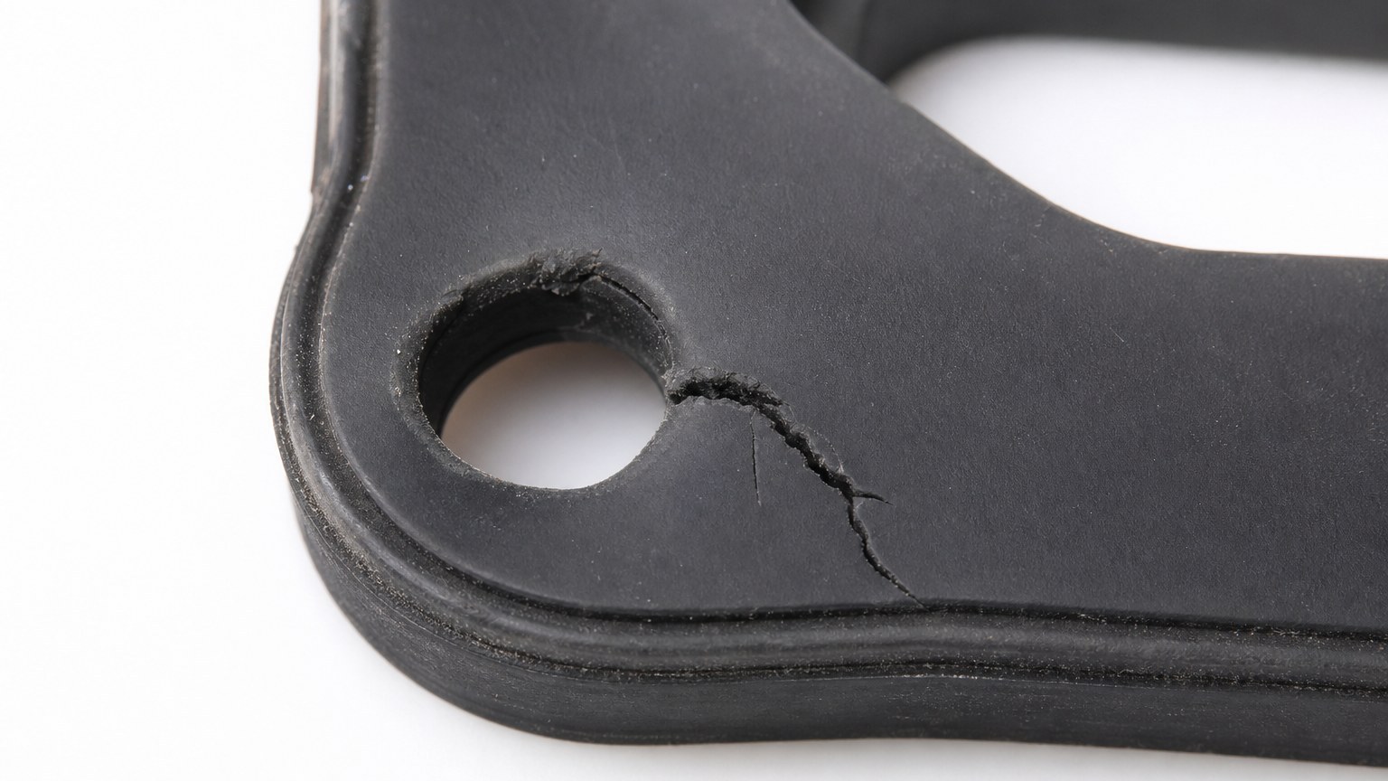
Where the tear actually begins
Almost every tear we examine starts at the moulded edge of the hole rather than somewhere in the middle of the wall. That is not an accident of where the load is highest. It is where the geometry is least forgiving.
The hole edge is a notch by default
A moulded hole has a parting line, a small radius, and often a slight flash ridge where the core pin met the cavity. Each of those is a stress riser. In a tensile test coupon the failure usually starts at an edge for the same reason: the material is uniform, but the stress is not.
This is why the same compound can pass a tensile test comfortably and still tear at a hole in service. The material property is fine; the local geometry is concentrating the load into a very small volume of rubber.
Installation stretches the hole before the joint closes
When a gasket is pushed over a screw or a spigot, the hole has to open. The stretch is not uniform: the material immediately around the hole takes most of the strain, and the strain is highest on the side facing the direction of the push. If the hole is undersized relative to the fastener, that local strain can exceed the elongation the compound can recover from, and the edge whitens before it cracks.
Whitening is an early warning, not cosmetic damage
A white or chalky band around a hole after assembly is not surface marking. It is the visible sign of polymer chains being stretched past their elastic limit. Parts that show it will usually crack within a few assembly cycles even if they survive the first one. If your inspection finds whitening at the holes, the hole size or the installation method needs changing before anything else is adjusted.
How much material around the hole is enough
There is no single ratio that fits every gasket, and treating one as a rule is how parts end up either fragile or unnecessarily bulky. What can be stated is what the remaining material has to do: carry the installation load without yielding, and keep the sealing land continuous.
Practically, the dimension to look at is not the wall thickness alone but the narrowest path between the hole and the nearest free edge or neighbouring hole. A hole placed close to the outer edge leaves a short, highly loaded bridge. A hole placed between two other holes leaves a bridge loaded from both sides. Both fail earlier than a hole in open material, even when the nominal wall thickness is identical.
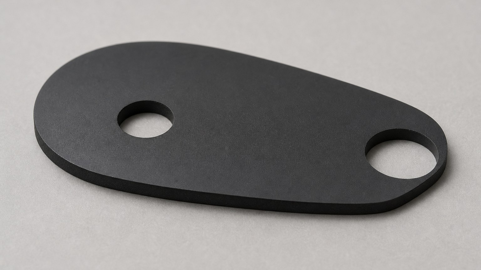
Compare the two holes here. On the left, the material around the opening has room to distribute the load. On the right, the hole sits near the edge and only a thin strip of silicone remains between the hole and the outside.
When that strip tears, the seal path is broken immediately — the crack does not need to grow far. This is why hole position deserves as much attention as hole diameter during layout.
A useful way to check it is to draw the load path rather than the wall thickness. Trace from the fastener, through the material, to the nearest sealing surface. If that path passes through a section narrower than roughly the hole diameter, the area is worth a second look — not because a number says so, but because that is where the strain will concentrate when the part is installed.
Why the corner radius changes more than the wall
Rounded internal corners are usually described as good practice. The reason is mechanical: a sharp corner concentrates stress over a very small area, while a radius spreads the same load over a longer length of material. On a thin section, that difference is the gap between a part that survives handling and one that does not.
The effect is strongest where a hole meets the outer contour or where two cut-outs come close together. In those places the radius is doing two jobs at once — it is both the corner of the hole and the transition to the outer edge.
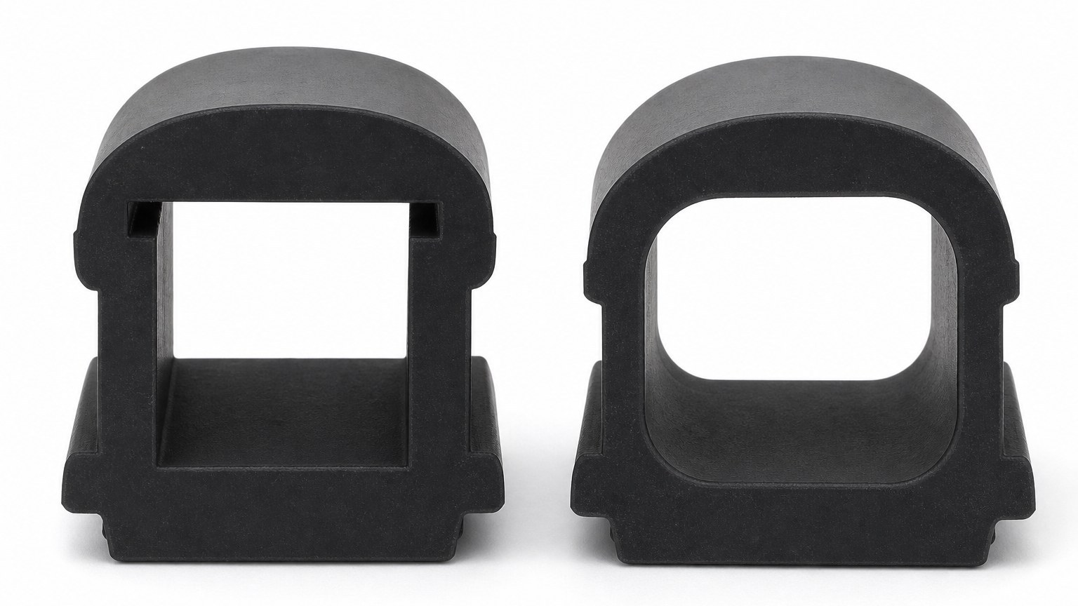
The two sections below are the same size and the same compound. The left one has square internal corners; the right one has a generous radius. Under a lateral pull, the left one starts to tear at the corner, while the right one deforms over a longer arc before the material reaches its limit.
When we revise a tool for this reason, the radius change is usually small in absolute terms and has no effect on the sealing function, which is why it is one of the cheapest durability improvements available.
Hardness, tensile strength and tear strength are not the same property
The instinct when a gasket tears is to specify a harder compound. Hardness does affect tear behaviour, but it is not the same measurement, and changing it can make the part worse in other ways.
Hardness describes resistance to indentation. Tensile strength describes the stress at which the material breaks when pulled. Elongation describes how far it stretches before that happens. Tear strength describes how much energy is needed to propagate an existing cut. A gasket at a hole is failing in the fourth mode, which is why a compound with good tensile numbers can still tear at an edge.
For reference, published ranges for general-purpose silicone sit around 6.5–10.5 MPa tensile with 380–620% elongation, while high-tear grades reach roughly 9.5–13 MPa with elongation above 500%. Those figures come from our comparison of tensile strength and tear resistance in silicone and FKM seals, and they are typical values rather than a specification for any particular part. What matters for a gasket with holes is the combination: enough elongation to install without yielding, and enough tear resistance to stop a small edge defect from growing.
Softer compounds are not automatically more tear-resistant. A 40 Shore A silicone stretches further before breaking but also has less resistance to a propagating crack once one starts. On a thin bridge between two holes, that trade can go the wrong way.
The installation direction decides which edge fails
Two identical gaskets installed from opposite sides will fail at different places. The edge that faces the direction of travel takes the strain first, and if the fastener has a thread, chamfer or burr, that edge is also the one being scraped.
This is worth controlling in the assembly instruction, not only in the drawing. Where the design allows, orient the gasket so the insertion load lands on the thicker side of the hole land, and specify a chamfer or radius on the fastener that meets the seal. A deburred screw costs nothing and removes a common starting point for tears.
Repeated assembly makes this worse in a way that single-cycle testing hides. A gasket that is opened for maintenance twice a year will see ten insertion cycles over five years; each one takes a little elongation out of the material around the hole.
Checking hole design before the mold is cut
Most silicone gaskets that fail at a hole would have passed if these checks had been made on the drawing instead of on the sample, because every one of them changes the tool.
- Measure the narrowest remaining strip between each hole and the nearest free edge, and between adjacent holes.
- Check every internal corner for a radius; specify it on the drawing rather than leaving it to the toolmaker.
- Compare hole diameter with the actual fastener, including thread and chamfer, not only the nominal screw size.
- Confirm the direction of installation and whether the part will be assembled by hand or by fixture.
- Decide whether the joint will be reopened in service, and if so, how many cycles the design should survive.
- Check the tolerance stack: a hole at the low end of its tolerance with a fastener at the high end can double the interference.
What we check when a torn gasket arrives
When a customer sends a failed part, the first question is where the crack started, and the second is what the hole looked like before installation. A clean edge with a single origin point suggests a geometry problem. A ragged edge with several origins suggests demoulding damage, which is a production issue rather than a design one.
From there we compare the measured hole and wall dimensions with the drawing, look at the parting line position, and check whether the tear follows the flash. In a surprising number of cases the answer is a hole placed one or two tenths too close to an edge — a change that costs nothing on the drawing and everything after tooling.
Our plant in Dongguan runs its own tool shop alongside 32 compression presses, so a revised hole layout can be tested on a prototype tool before production tooling is re-cut. Tolerances follow ISO 3302-1 classes, with M2 achievable on smaller parts and M3 as the commercial default, and shrinkage is compensated at roughly 2% so hole positions land where the drawing says.
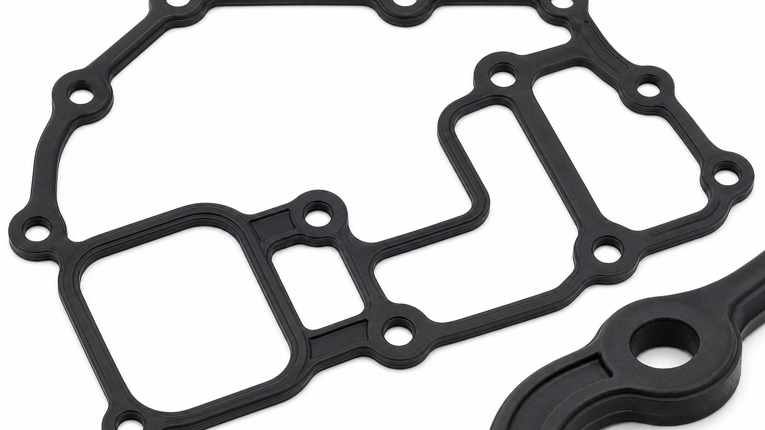
A layout like this one looks simple and is where most tear problems are created. Every hole leaves a bridge to its neighbour, and the narrowest bridge sets the handling strength of the whole part.
When a design has to keep all its holes, widening two or three of the critical bridges is usually enough, and it can often be done by moving a hole by a fraction of a millimetre rather than by changing the outline.
In short
Tearing at an inner hole is a geometry problem with a material component. The hole edge concentrates stress, installation stretches the local material, and a thin bridge or a sharp corner decides whether that stretch turns into a crack. Changing compound is the slowest and most expensive way to address it; changing the hole position, the radius or the installation direction is usually faster and more reliable.
If you are dealing with a gasket that has already torn in the field, send the part or a photo of the fracture origin together with the drawing to our engineering inquiry page. The origin point usually tells us which dimension to change before we cut anything.
For drawings and questions by email: nani@fromrubber.com or karl@fromrubber.com. WhatsApp and WeChat: +86 18676210913.
Common questions about tears at inner holes
Why do silicone gaskets tear at the mounting holes?
The hole edge is the thinnest section, carries the highest installation strain, and has a moulded edge that behaves like a notch. Stress concentrates there before anywhere else on the part, so that is where a crack starts.
How much material should be left around a hole?
There is no universal ratio. What matters is the narrowest path from the hole to a free edge or a neighbouring hole: when that bridge is narrower than the hole diameter, the layout is worth reviewing before tooling.
Does a softer silicone prevent tearing?
Not on its own. Softer material stretches further before breaking but resists crack growth less. Tear strength, elongation and section geometry decide the result, which is why hole position and corner radius usually matter more than hardness.