Key Design Challenges of Silicone Buttons for Angle Grinders
Six drawings into a grinder programme and the panel still does not feel right. The keys are stiff through a work glove, the lock key registers when the tool is set down on a bench, and one printed icon sits visibly proud of the housing line. None of that is a moulding fault. It is what happens when four design conflicts are left open until the tool is already drawn, and the keypad is asked to settle all four at once.
A keypad is where the rest of the tool's tolerances end up
The keypad sits between a rigid housing and a rigid switching element, and it is the only soft part in that stack. When the housing aperture is moulded slightly off centre, when the switching element sits a fraction high, when the base plate runs a little thick, none of those deviations disappear. They arrive at the keypad, and the keypad absorbs them. Two things follow. The first samples feel wrong, and a later production batch feels different from the first one even though nothing on the drawing changed.
The practical answer starts with a number rather than another view. ISO 3302-1 sets out classes of dimensional tolerance for moulded rubber products, running from the fine classes through to the general commercial grade. A silicone keypad quoted to a fine class is a different job from one quoted to the general commercial class: different mould maintenance, different cavity layout, a different inspection rule. If the class is missing from the drawing, the moulder prices the version of the job that is easiest to make, and the toolmaker aims at whatever the press will hold on that day.
Put five lines side by side before comparing keypad drawings: tolerance class, hardness band and test method, force band per key group with a release-force floor, sealing method, and legend process. On most angle grinder panels at least two of the five are unstated, and the gap between two samples usually starts there rather than in the mould.
Conflict one: the force a glove can feel is the force that mis-triggers bare-handed
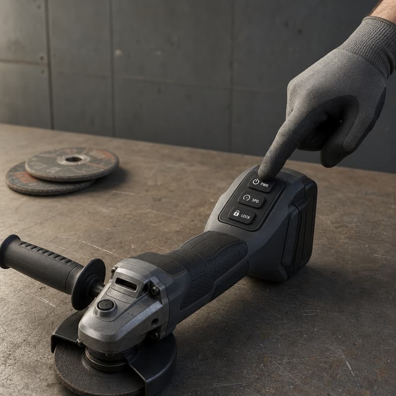
Grinder keypads get pressed by a gloved thumb, and the same panel gets bumped when the tool is laid down on its side. Push the force up until a glove can read it and the panel starts accepting taps nobody intended as inputs. Leave it low and the operator presses twice, or presses harder and shorter, which is how a contact element reaches its cycle limit early.
The release force decides how the panel feels in the field
Actuation force is what gets specified. Release force is what gets felt. A key that takes a certain load to close and gives most of it back on the return feels crisp on a bench and vague through a glove, because the operator reads the press from the return as much as from the break-over. On gloved applications the release-force floor belongs on the drawing next to the actuation band, and it belongs per key group rather than as one panel-wide target, because the power key, the speed key and the lock key are not pressed in the same way.
Hardness sits underneath all of this. Hardness is measured by ASTM D2240, with ISO 48-4 as the international equivalent, and the width of the band matters as much as the nominal point. A band of plus or minus three points against a band of plus or minus five points is a different level of process control at the press and a different acceptance rule at inspection.
Conflict two: a shallow handle, and a key that still has to travel
Handle depth on a grinder is fixed by grip, by the trigger and by the battery interface, and it is normally locked before the keypad drawing starts. Travel comes from three places at once: deflection of the silicone web, inversion of the element underneath, and compliance in whatever the key lands on. A sealing lip consumes part of that travel before the operator feels anything at all, so the budget has to be split deliberately rather than discovered on the first sample.
Travel written as one number usually turns into two problems
When a drawing gives only total travel, two things tend to go wrong. The web gets thinned to hit the number, which lowers the return force toward the end of the service life. The sealing lip gets compressed further than intended, which raises the break-over force and shortens seal life. Splitting the budget into web deflection, element inversion and seal compression makes the trade visible while it is still on paper, and it gives the moulder three numbers to test against instead of one.
Conflict three: five legends in a strip a gloved thumb has to find
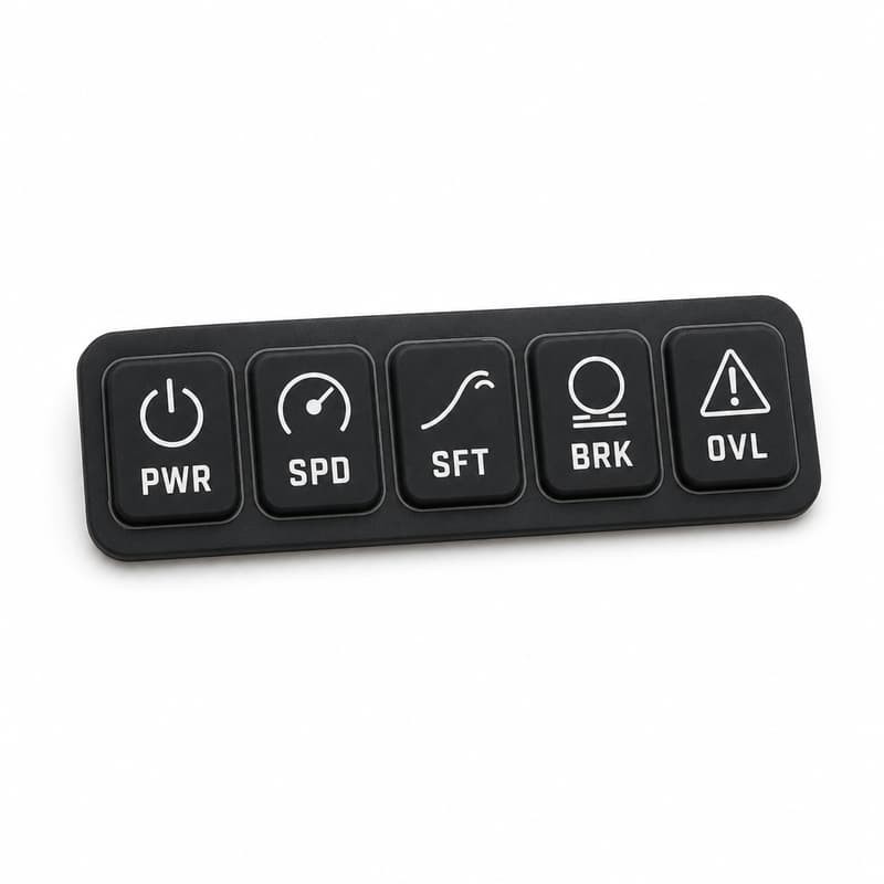
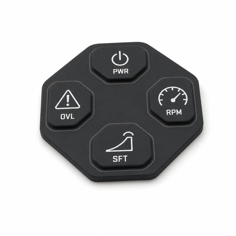
Key count on a grinder panel is set by function: power, speed, soft start, brake, overload, lock. Fitting them into a strip reachable without moving the grip produces a key pitch that is smaller than a gloved finger pad. That is a legibility problem before it is a printing problem, and it gets worse when every key carries both a symbol and a word.
Printing adds a second constraint. Screen printing registers against a moulded feature, so where the parting line falls on the key face changes how the legend lands, and cavity-to-cavity variation shows up earlier on a five-key strip than on a two-key one. Parting line position is worth settling with the mould maker rather than after first article, because moving it afterwards is a tool change.
Cutting legend density without cutting function
Three levers work better than shrinking type. Shape coding gives the keys distinct outlines so position and profile carry meaning at arm's length. Symbol-led legends read faster than abbreviations and survive a smaller print area. Reserving words for the two safety-relevant keys keeps the type large where it matters most. None of the three changes the electrical design; all three change what has to be printed, and what has to survive abrasion afterwards.
Conflict four: sealing against the dust the tool makes itself
A grinder is a dust source. The keypad sits on the outside of the tool, in the path of its own debris, and any gap between the keypad flange and the housing becomes a route inward. IEC 60529 defines the dust degrees of protection: IP5X is dust-protected, where dust may enter but not in a quantity that interferes with operation, and IP6X is dust-tight, tested in a dust chamber with the enclosure under reduced pressure, up to 2 kPa in the method described by the standard. Which one a panel needs is a decision about the application rather than a label, and it has to be made before the seal geometry is drawn.
The conflict is that sealing adds force. A lip stiff enough to keep abrasive dust out is stiff enough to raise the break-over force, which pushes straight back into conflict one. The usual resolution is to separate the two jobs: one feature seals, a different feature sets the force, and neither is asked to do both.
Retention has to be settled at the same time. A flange that creeps under load lets the panel relax, the key rests lower, and the force band drifts after a few months in service. That is a compression set question, and ISO 815-1 or ASTM D395 is the way to put a number on it rather than a bench opinion.
What to settle before the tool is cut
- Tolerance class to ISO 3302-1, stated on the keypad drawing rather than left to the moulder.
- Hardness nominal and band, with the test method named, ASTM D2240 or ISO 48-4.
- Force band per key group, plus a release-force floor for the gloved-use case.
- Travel split across web deflection, element inversion and seal compression.
- Ingress target for the assembled panel, not only for the keypad as a part.
- Legend process, and the abrasion rule that will be used to accept it.
- Retention method, and what keeps the flange flat across the service temperature range.
How the pattern shows up in a design review
Grinder panels reach the moulding stage in fairly consistent condition. The housing is tooled or close to it, the key layout is fixed by the electronics, and the keypad is expected to make the assembly work. The reviews that go well tend to ask the same three questions early.
First, which single feature sets the force and which single feature does the sealing, so neither has to compromise for the other. Second, what happens to force after the panel has sat compressed in a hot tool bag for a week, which is a compression set question rather than a spring question. Third, how the legend will be accepted, so that abrasion resistance gets a number attached to it instead of an opinion.
One grinder programme changed only two things and stopped chasing feel from sample to sample. The web under the lock key was reprofiled so the lock key sat outside the force group of the working keys, and the release-force floor was written into the drawing for gloved use. The mould was not touched after that. The rest of the work was inspection: naming the tolerance class and the hardness method so that the second batch could be compared with the first, rather than with a memory of how the first felt.
On the electrical side the boundary is worth stating plainly. The silicone keypad carries the contact element that closes the circuit, and its position and force have to match the board underneath it. The board itself, meaning its footprint, its pad layout and its copper, is the customer's electronics design. A keypad supplier works to that drawing, and changing the silicone cannot correct a footprint that sits in the wrong place.
Questions that come up in nearly every grinder panel review
Should the keypad be designed before or after the housing?
After the housing aperture and the switching plane are fixed, but before the housing mould is cut. Designing the keypad last means it absorbs every upstream tolerance with no budget left to do it. Designing it first usually produces a keypad that cannot be assembled. The workable order is to freeze the switching plane, then size the keypad stack, then confirm the aperture.
Is a harder silicone the answer to a key that feels too soft?
Rarely on its own. Hardness changes how the web feels, but force also depends on web thickness, element geometry, contact height and seal compression. Raising hardness to correct force commonly makes the return worse and moves the dust sealing problem instead of solving it. That is why force and hardness are two separate lines on the drawing.
Where does the printed circuit board fit into this?
It sets the position the key has to reach and the travel available before contact. From the silicone side the parameters that matter are contact element height, pad flatness and the force at which contact is made. The switch design and the circuit layout stay with the electronics team, and keeping them on separate drawings is what allows a keypad to be requoted without touching the board.
FromRubber (Dongguan Bohao Electronic Technology Co., Ltd.) moulds custom silicone keypads and rubber keypads for hand-held tools and industrial panels, and reviews keypad stack-ups against the housing aperture and switching plane before tooling starts. The notes above come from that review work and from the standards listed below.
Related reading
Sources
- [1] IEC 62841-2-3:2020, Electric motor-operated hand-held tools, transportable tools and lawn and garden machinery - Safety - Part 2-3: Particular requirements for hand-held grinders, disc-type polishers and disc-type sanders, including rated no-load peripheral speed limits. https://webstore.ansi.org/standards/ds/dseniec628412021-2444959
- [2] iTeh Standards, EN IEC 62841-2-3:2021 catalogue entry confirming scope for angle, straight and vertical grinders up to 230 mm rated capacity and the 80 m/s peripheral speed limit. https://standards.iteh.ai/catalog/standards/clc/f2639a9a-2e9e-4301-8b8b-36086fac65ce/en-iec-62841-2-3-2021
- [3] ISO 3302-1:2014, Rubber - Tolerances for products - Part 1: Dimensional tolerances, classes M1 to M4 for moulded rubber products. https://www.iso.org/obp/ui/#iso:std:iso:3302:-1:en
- [4] Industrial Rubber, ISO 3302-1:2014 rubber tolerances for products: dimensional tolerance classes M1 to M4 for moulded solid rubber products. https://www.industrial-rubber.com/news/iso-3302-12014-rubber-tolerances-for-products-part-1-dimensional-tolerances/
- [5] Zorge, DIN ISO 3302-1 rubber lexicon, four tolerance classes from M1 fine to M4 coarse. https://www.zorge.com/en/rubber-lexicon/din-iso-3302-1/
- [6] ASTM D2240-15(2021), Standard Test Method for Rubber Property - Durometer Hardness. https://www.astm.org/d2240-15r21.html
- [7] ISO 48-4:2018, Rubber, vulcanized or thermoplastic - Determination of hardness - Part 4: Indentation hardness by durometer method, the international equivalent of Shore hardness testing. https://www.iso.org/obp/ui/ru/#!iso:std:74969:en
- [8] NAMSA, ASTM D2240 durometer hardness test description, including sample conditioning and Shore A and D scale selection. https://namsa.com/services/testing/tests/astm-d2240-durometer-hardness/
- [9] Castle Compliance, IEC 60529 ingress protection testing, definition of IP5X dust-protected and IP6X dust-tight, and the 2 kPa reduced-pressure dust chamber method. https://castle-compliance.com/iec-60529-testing/
- [10] ISO 815-1:2014, Rubber, vulcanized or thermoplastic - Determination of compression set - Part 1: At ambient or elevated temperatures. https://www.iso.org/standard/61761.html
- [11] ASTM D395, Standard Test Methods for Rubber Property - Compression Set, 25 percent deflection method used in elastomer selection. https://www.sciencedirect.com/topics/engineering/compression-set
- [12] Custom silicone keypad engineering guide covering actuation force, conductive contact options and surface coating selection. https://www.siliconefactories.com/custom-silicone-keypads-engineering-guide/