Industrial Silicone Panel Pad: What Works and What Doesn't?
The mold is cut. The first articles look perfect on the bench. Then the sample arrives and three of the twelve keys do not click, or click twice, or click only in the corner. Nobody can explain it, because "the drawing is fine." The drawing was always fine. The geometry rules that were not on the drawing are what failed. This article is the rules list we actually use when a silicone panel pad has to feel right, molded in volume, batch after batch.
What works: the rules that keep a panel pad consistent
Force comes from geometry, not from the hardness number alone
The web — the thin membrane ring around each key — is where actuation force is born. The practical working band for web thickness on a tactile keypad is roughly 0.3–0.8 mm, tuned together with the dome profile [1]. Two keys on the same pad, same durometer, can differ by 40 g of actuation force if their web thickness differs by a tenth of a millimeter. So the first rule is: keep the web uniform on each key, and let the dome and skirt do the tuning. Durometer selection (typically 40–70 Shore A, measured per ISO 7619-1 on a molded slab) sets the material band; geometry sets the feel [2].
Design the snap, then verify it
Target the classic band: peak actuation force 125–150 g with a snap ratio of 40–60% [3]. Then verify it on finished parts with a force-travel curve, not on a drawing. The snap ratio is the difference between "clicks" and "mush," and it is a measured number, not a feeling.
Mold the alignment in, do not glue it
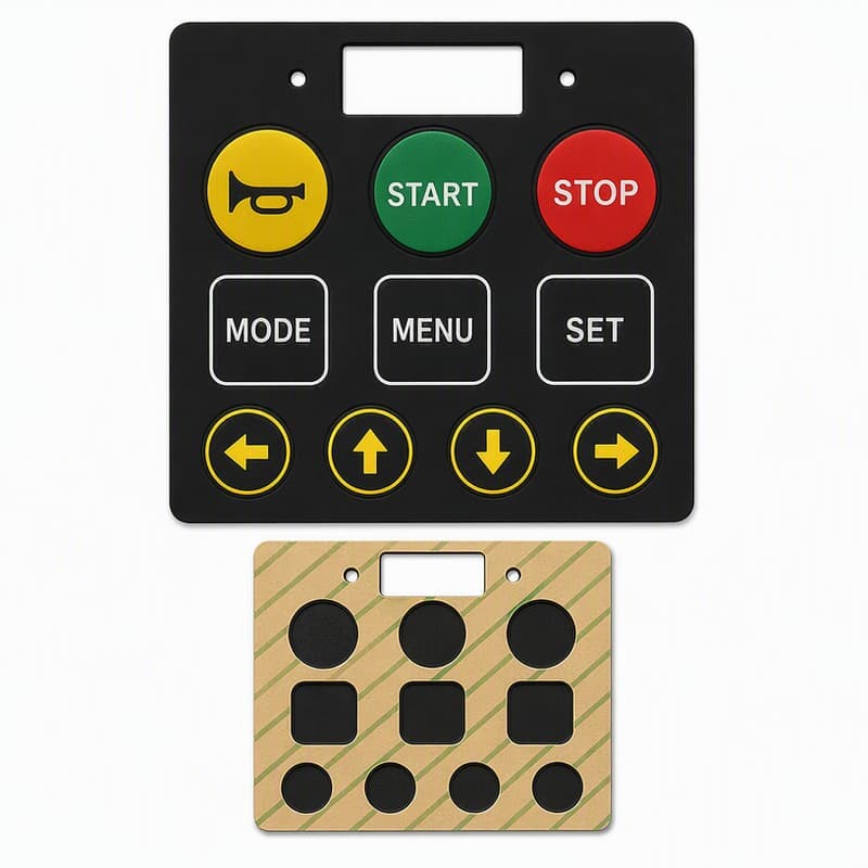
Locating ribs, pins and pockets molded into the pad index it to the housing or PCB. They remove the alignment variable from assembly, which matters because the conductive pill under each key has to land on its pad within a fraction of a millimeter. Relying on adhesive for alignment turns every assembly into a judgment call.
Keep legends away from the flex zone
Printed or laser-etched legends need a keep-out zone around the web and dome. A legend printed onto the flexing web cracks first and looks like a material defect. The rule: legends sit on the key top and the flat pad area; the web ring stays clean.
Put the parting line where nobody presses
Flash on the dome edge or the web changes the force curve. The parting line should run along the pad periphery or the key sidewall, away from the tactile surface, and the flash spec should say so explicitly. Cheap molds flash exactly at the dome edge, and the feel change is invisible on the drawing.
Vent the cavity, or the legends will tell you
Trapped air under a printed legend shows up as bubbles and pinholes, and on a backlit panel it looks like a quality catastrophe. Proper venting plus a controlled closing speed prevents it at the mold stage. When a backlit pad shows pinholes, the first question is not the ink; it is the venting.
What does not work: the habits that fail in production
Uniform wall thickness everywhere
"Keep the wall uniform" is good advice for plastic molding and wrong for silicone keypads. A pad molded at uniform 1.5 mm thickness everywhere produces keys that are stiff, heavy and mushy, because there is no thin web to snap. Silicone pads need intentional thickness variation: thin webs, domed keys, thick base. Treating the pad like a flat gasket is the most common cause of "no click" panels.
Specifying hardness without a force-travel curve
A durometer number on the drawing is not a feel specification. Hardness tested on the finished pad reads harder than the compound's datasheet, because the durometer needle bottoms into a 1–2 mm wall while the test method assumes a slab about 6 mm thick (ASTM D2240) [2]. If the spec says only "60 Shore A," the supplier can hit the number and ship a pad that feels wrong. Put the force target and tolerance on the drawing instead.
Carbon pills on thin edges
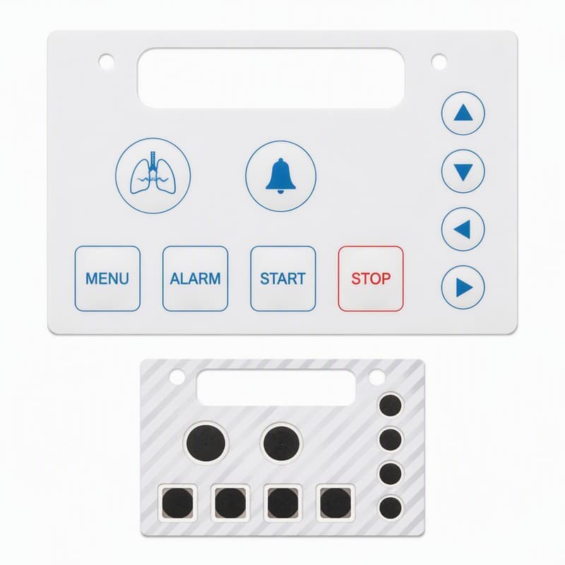
The conductive pill needs material under it. Placing pills where the pad tapers to a thin edge invites the classic edge-thinning failure, where the pill region thins, the contact pressure drops, and the key becomes intermittent (we documented a 22% failure rate from exactly this). The rule: design a full-thickness boss under every pill, and check the thickness after molding, not only in the drawing.
Over-constraining the pad in the housing
Silicone expands and contracts several times more than the surrounding plastic. A pad force-fit into a tight pocket binds in the cold and bulges in the heat. Leave the pad freedom to move in the plane, and control position with ribs, not with interference everywhere.
Ignoring mold wear
Steel wears; web thickness drifts; feel changes. After tens of thousands of shots, a cavity that produced 150 g keys can produce 180 g keys without anyone changing a number on the drawing. This is why in-process force-travel testing matters: it catches cavity wear as a trend, not as a field failure.
A panel pad that clicked wrong, and what actually fixed it
A customer's panel pad — twelve keys, backlit, for a process controller — came off the line with three keys that clicked inconsistently: sometimes crisp, sometimes linear, occasionally double-actuating. Incoming inspection showed no missing legends, no flash visible to the eye, and a durometer reading inside spec.
The force-travel curves told the story. The three bad keys measured 30–60 g above their sisters, and the snap ratio had dropped below 30%. The mold was then inspected cavity by cavity: the web ring on those keys had worn thin by about 0.08 mm, and a thin line of flash ran along one dome edge. The compound, the hardness, and the drawing were all exactly as specified. The cavity was the problem.
We re-cut the affected cavities, added a flash-control step to the process sheet, and put a force-travel check on the line for every batch. The spread across the twelve keys narrowed from ±60 g to ±15 g, and the double-actuation complaints stopped. The lesson was cheap, because it happened on samples. The same failure found in the field would have cost the customer a recall of a control panel, not a mold re-cut.
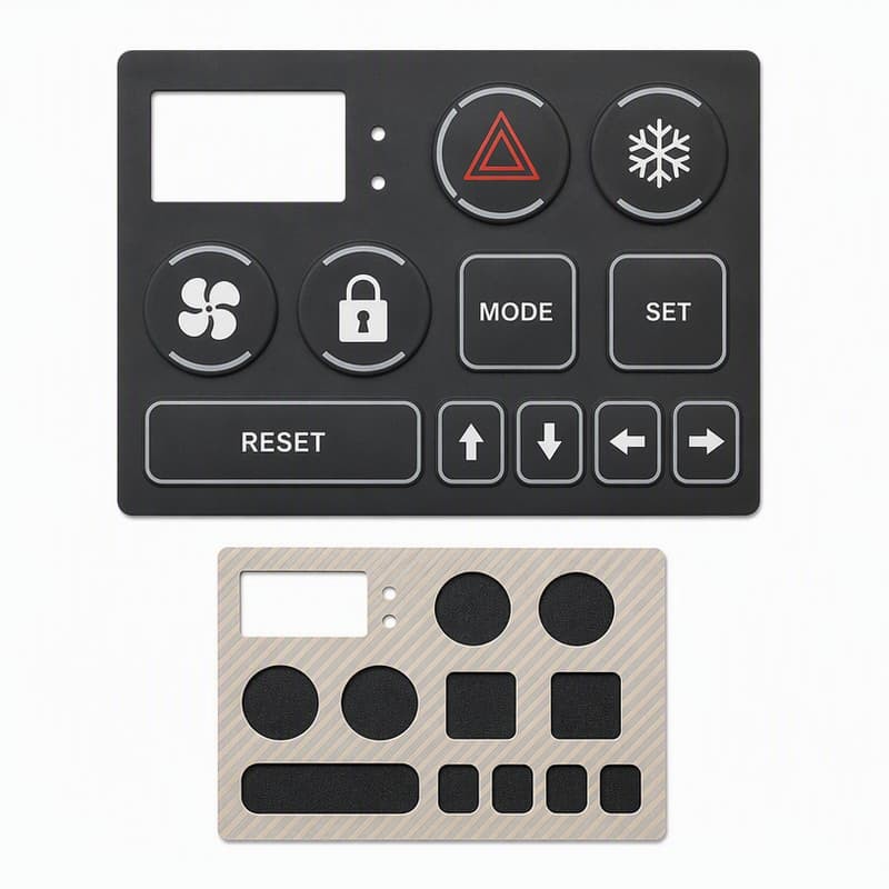
The inspection list that catches these before shipping
- Force-travel-snap on finished parts, every batch, with the tolerance written down (±25 g band; snap ratio 40–60%).
- Web thickness measured on the molded part at the critical keys, not just at the gate.
- Pill boss thickness and contact resistance per batch (ISO 1853 for resistivity, plus a finished-pill contact check).
- Legend inspection after an alcohol rub and an abrasion pass, per the legend spec.
- A durometer check on a molded slab from the same lot, not only on the finished wall.
- Cavity wear trending: if the force curve drifts, the mold goes back to the toolroom before the parts do.
FromRubber builds custom silicone keypads and panel pads as a full process: compound, tooling, molding, and in-process force-travel testing on finished parts, with the durometer verified on the batch slab. We do not make PCBs; we make the pad that has to land on yours, and we document that interface so the tolerance belongs to someone. If a panel pad feels wrong and you cannot tell whether it is the web, the dome, the pill, or the mold, send the part and the failure description — we will measure it and tell you which.
Sources and test references used in this article:
- Web thickness working band 0.3–0.8 mm and web-angle design practice for tactile silicone keypads per keypad engineering references (Jasper Electronics silicone rubber keypad design guide, 2026; Diamond HMI rubber keypad design guide).
- ISO 7619-1, Rubber, vulcanized or thermoplastic — Determination of indentation hardness — Part 1: Durometer method; ASTM D2240, which assumes a specimen thickness of at least about 6 mm, while finished keypad walls are typically 0.8–2 mm.
- Diamond HMI, Rubber Keypad Design Guide: actuation force 125–150 g, snap ratio 40–60%; Plastec silicone keypad design reference reports the same band.
- ISO 1853, Conducting and dissipative rubbers, vulcanized or thermoplastic — Measurement of resistivity.