How Do Button Size and Spacing Affect Silicone Keypads on Vibration Analyzers?
A vibration analyzer is usually operated with one hand. The other hand holds the probe against a bearing housing, and the eyes are on the reading, not on the keypad. In that posture, the only thing standing between a correct measurement and a wrong one is whether the thumb lands on the intended key without looking down.
That makes button size and spacing a functional question rather than a cosmetic one. A key that is 2 mm too small does not look wrong on a drawing, and a gap that is 1 mm too tight does not raise an alarm in CAD. Both are obvious the first time someone presses the panel with a gloved thumb while holding a probe steady.
This article deals with the dimensional side of a silicone keypad on a handheld measurement instrument: how size changes access, how spacing is actually measured, and how the two interact with material and mold before the layout is frozen.
In short: a key is easy to hit when the clear gap between adjacent keys is a visible fraction of the key size and the contact patch of the intended glove fits inside that gap. Center-to-center distance does not describe this; edge-to-edge clearance does, and both belong on the drawing.
How Does Button Size Affect Silicone Keypad Operation?
Button size sets the contact area available to a finger. That area has to absorb the natural scatter of where a thumb lands: nobody hits the same square millimeter twice, especially not while holding a probe with the other hand. When the contact area is generous, the scatter is absorbed. When it is tight, the scatter becomes an adjacent press.
Size also sets how much panel the key consumes, and a keypad has a fixed budget. Making every key larger is not a solution on a handheld analyzer; it moves the problem from pressing accuracy to function count.
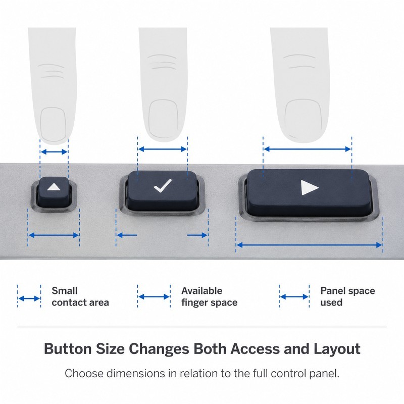
The three keys above use the same panel height. Only the top face changes, and with it the amount of panel left for neighbours and for the edge of the housing.
Buttons That Are Too Small May Be Difficult to Press Accurately
A small key is not only harder to hit; it is harder to hit without touching the key beside it. If the contact patch of a gloved thumb is wider than the key plus half the gap on each side, the press will sometimes register on the neighbour first. The operator experiences this as a key that occasionally does the wrong thing, which is worse than a key that is simply stiff.
The usual response is to increase the gap, but that spends panel area that could have gone into the key itself. On a compact instrument, slightly larger keys with the same gap often improve accuracy more than the same keys with wider gaps.
Oversized Buttons Can Reduce the Space Available for Other Controls
Every millimeter added to a key has to come from somewhere. Once a key grows, its neighbours move outward or shrink, and the panel edge moves closer. On instruments where the keypad shares the front face with a display, a connector or a label, the layout quickly runs out of room and the design starts borrowing space from the enclosure.
Button Height Also Influences Accessibility and Tactile Recognition
Size in plan view is only half the story. A larger top face helps a finger find the key; a higher profile helps the finger confirm it. The two work together, and a very flat key with a large face can still be hard to locate because there is nothing to feel at the boundary.
Height is limited by the panel and by how the instrument is carried, so the practical range is narrow. Within that range, a key that stands clearly proud of its neighbours reads better than a larger key that sits flush.
Why Does Button Spacing Matter on a Compact Vibration Analyzer?
Spacing is usually specified as a center-to-center distance because that is what the drawing already shows. But the number the operator experiences is the clear gap between edges. Two keys at a 12 mm center distance with 10 mm tops leave 2 mm of separation, and 2 mm is not something a gloved finger can feel.
That gap does three jobs at once: it separates the tops so the finger can identify boundaries, it allows a press to be aimed, and it gives the silicone web enough room to flex without dragging the neighbouring key down with it.
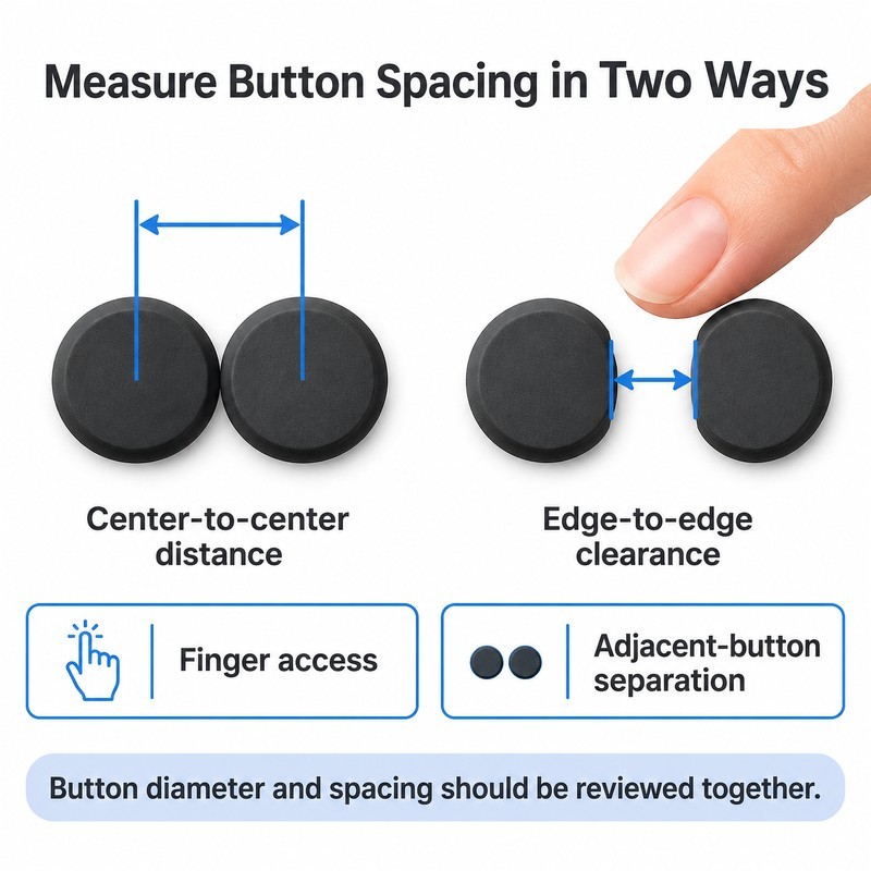
The two measurements above describe the same pair of keys. A layout can look acceptable in center distance and still be tight in clearance, which is why the gap belongs on the drawing as a controlled dimension.
Insufficient Spacing Can Increase the Risk of Pressing the Wrong Button
When the gap is too small, the silicone between two keys becomes a shared hinge. Pressing one key pulls the web that belongs to the other, and the switch underneath may close early or feel ambiguous. The operator notices this as a key that occasionally triggers with a neighbouring press, which is a layout problem showing up as an electrical one.
Excessive Spacing Can Make the Keypad Larger Than Necessary
The opposite mistake is just as common on instruments where the panel was sized early and the keypad was fitted later. Wide gaps push keys toward the edges, reduce the room available for a thumb to rest without pressing anything, and make the panel look emptier than it is. On a handheld device, wasted panel area is carried weight.
Button Center Distance Should Be Evaluated Alongside Button Diameter
Center distance alone cannot be judged. A 15 mm center distance is generous with 8 mm keys and cramped with 13 mm keys. The useful ratio is clearance against key size: the gap should be a visible fraction of the key, not a rounding error at the edge of the tolerance.
Both numbers also depend on the intended user. A bare-finger panel on a bench instrument tolerates tighter clearance than a gloved panel on a field instrument, because the contact patch is smaller and the aiming motion is more controlled.
| Dimension on the drawing | What it actually controls | What it does not tell you |
|---|---|---|
| Center-to-center distance | Overall layout and how much panel the keypad occupies | The gap a finger can feel between two keys |
| Edge-to-edge clearance | Separation between keys and the risk of an adjacent press | The contact area available on the key itself |
| Button top area | Whether the intended glove fits on the key | How far the next key sits from that contact patch |
| Button height | Tactile confirmation at the key boundary | Whether the bezel or carry case limits the protrusion |
How Should Engineers Balance Button Size, Spacing, and Panel Dimensions?
The balance is easier when it is done in a fixed order. Most layout problems come from starting with a key diameter that was carried over from a previous product, then fitting the function list around it.
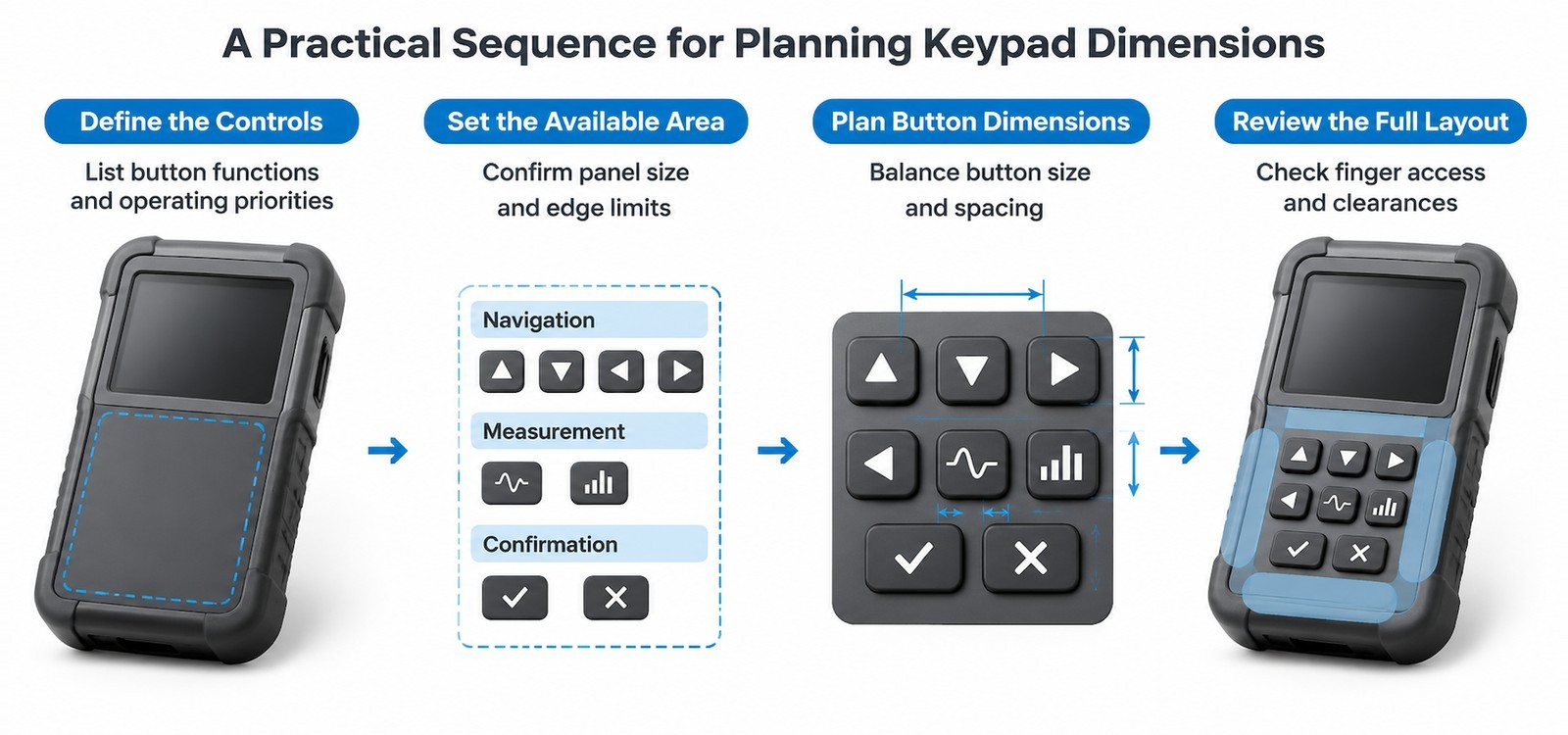
Start With the Total Number of Controls and Their Functions
A complete control list, sorted by how often each key is used, decides how much area each function deserves. Measurement and navigation keys that are used constantly justify more space than a calibration key that is opened once a month. Without that ordering, every key tends to end up the same size, which wastes area on the least-used functions.
Give Frequently Used Buttons Enough Room for Easy Access
Frequency should drive both size and position. The most-used keys belong where the thumb rests naturally, with the largest clearance around them. Rarely used keys can be smaller and closer together, provided they are still identifiable and still reachable without moving the hand.
Consider Whether the Analyzer Will Be Operated With Gloves
Glove use changes the numbers more than any other single factor. A nitrile or leather glove widens the effective contact patch and reduces the ability to feel small height differences, so both key size and clearance need to grow. If the instrument is used in a plant, assume gloves for at least part of its life and test the layout that way.
Check the Clearance Between Buttons and the Panel Edge
Outer keys are the ones that get pressed by a thumb reaching across the panel, and they are also the keys closest to a bezel that may be higher than the keypad. A key that sits too close to the edge is hard to press without touching the housing, and the resulting off-axis press is exactly the motion that makes a nearby key trigger.
How Do Silicone Material and Button Structure Affect the Required Dimensions?
Dimensions are not independent of material. The same 10 mm key with the same 3 mm gap behaves differently in a soft compound and a firm one, because the web between keys deforms differently and the top face deflects differently under a thumb.
Silicone Hardness Influences How a Button Feels When Pressed
A softer compound spreads the load over a wider area and makes the key feel larger than it is, which can partly compensate for a small top face. A harder compound transmits force more locally, so the operator feels the exact edge of the key and presses more precisely, but with less tolerance for a mis-aimed thumb.
Button Diameter and Supporting Geometry Affect Structural Behavior
Increasing the top diameter without changing the base creates an overhanging crown that rocks under off-axis load. If a key grows by 2 mm, the base and the supporting wall usually need to grow with it, which in turn changes the gap to the next key. This is why a late size change is rarely a one-line edit.
Button Spacing Should Account for Mold and Assembly Requirements
Narrow gaps are harder to mold and harder to vent, and the material between two close keys can be thin enough to distort during demoulding. The same gap also has to accommodate the panel openings, so a dimension that works on the silicone drawing may not work once the panel cut-outs and their tolerances are considered.
What Button Layout Problems Should Buyers Identify Before Mold Development?
Three layout problems are worth hunting for on the drawing, because they are cheap to fix there and awkward to fix later.
Buttons May Become Difficult to Access When Their Edges Are Too Close
A 1 mm edge gap looks fine until the keypad is placed in a panel with a 0.3 mm clearance on each side. Suddenly the usable gap is smaller than the drawing suggested, and the outer keys are touching the bezel. Nominal dimensions should be checked against the assembled worst case, not the nominal panel.
Similar-Sized Buttons May Lack Clear Functional Separation
When every key is the same diameter and the same height, grouping can only be expressed by position. That works up to a point, but a row of five identical keys is easier to mis-hit than a group of four plus one clearly different confirm key. Separation is a layout tool, not only a spacing number.
Small Dimensional Changes May Affect the Entire Keypad Layout
Changing one key from 10 mm to 12 mm pushes its neighbours, which pushes the edge keys, which changes the perimeter. On a compact panel, a single size change can invalidate the whole layout, so it is worth confirming the key set before any individual dimension is optimised.
A quick sanity check before tooling: print the keypad at full size, cut the button circles out, and press them with the glove the instrument will actually meet. Clearance problems that survive a CAD review usually do not survive that test.
How Can Buyers Confirm the Right Silicone Keypad Dimensions?
Confirmation is a sequence, not a single approval. Each step catches a different class of error, and skipping the physical steps is what leads to a mold that matches the drawing and not the hand.
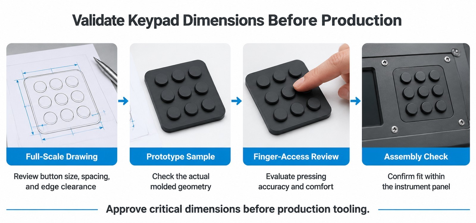
Review the Keypad Layout in a Full-Size Panel Drawing
Screen review hides scale. A full-size print on paper, placed in front of the person who will use the instrument, shows immediately whether the keys are reachable and whether the gaps read as gaps. It also exposes crowding that a 400 percent zoom view conceals.
Use Prototype Samples to Evaluate Finger Access and Pressing Accuracy
A molded sample answers questions about hardness, height and web behavior that no drawing can. Press it with the intended glove, in the intended posture, and count the mis-hits. Ten presses per key is usually enough to expose a layout that is too tight.
Check Button Clearance After Assembly
Clearance changes once the keypad is in the panel and the housing is closed. A key that moved freely on the bench can bind against a bezel that flexes slightly when the screws are tightened. This check belongs after assembly, not before.
Confirm Critical Dimensions Before Approving the Production Mold
Before approving tooling, confirm the dimensions that are functionally critical: perimeter fit, key heights, and the smallest edge gap on the panel. Everything else can tolerate more variation, and saying so explicitly keeps inspection focused where it matters.
What Should You Provide When Requesting a Custom Silicone Keypad Quote?
- Vibration analyzer model or application and how the instrument is held during use.
- Number of buttons and the function of each, with the most-used keys identified.
- Overall panel dimensions and the position of any display, connector or bezel.
- Individual button diameter or length and width.
- Center-to-center distance and the minimum edge-to-edge gap.
- Button height and the intended protrusion above the panel.
- Whether the instrument is used with gloves, and for what share of its life.
- Silicone hardness and color preferences, or the pressing feel required.
- Panel drawings or CAD files, including the panel cut-outs.
- Prototype and production quantities.
Frequently Asked Questions
What is a reasonable minimum gap between silicone keypad buttons?
There is no universal figure, because it depends on key size, hardness and glove use. The workable test is whether the gap is clearly visible as a fraction of the key and whether two adjacent keys can be pressed independently on a real sample.
Should spacing be specified as center distance or clearance?
Specify both. Center distance controls the layout, clearance controls the feel. If only one is given, the supplier has to guess which one the design actually depends on.
Can a keypad be made with different size buttons in the same row?
Yes, and it is often useful for grouping. The constraint is that the smaller key needs enough clearance on both sides, so the row's total height and the gap to the next row usually change too.
Does a larger button always improve pressing accuracy?
Up to a point. Beyond the size where the thumb sits comfortably, extra area mostly consumes panel space and pushes neighbours away, and the accuracy gain is small compared with the layout cost.
How does silicone hardness change the effective button size?
A softer compound deflects more under a thumb, so the contact area spreads and the key feels larger. A harder compound feels more defined at the edges. Neither changes the molded dimension, but both change how the dimension is experienced.
When should the panel cut-outs be confirmed relative to the keypad drawing?
At the same time. Keypad clearance and panel opening tolerance interact, and reviewing them together is the only way to know the worst-case gap before tooling.
Conclusion: Better Keypad Layouts Begin With Coordinated Dimension Planning
Button size and spacing cannot be optimised separately. Size sets the contact area, spacing sets the separation the finger can feel, and both are constrained by the panel, the material and the way the instrument is held. Planning them in the order controls, area, dimensions, review keeps the layout honest.
FromRubber supports instrument programs with dimensional review, button geometry development, silicone material selection, mold design and sample evaluation. On a handheld analyzer, the sample review is where most spacing questions are settled, and it is worth doing before the production mold is approved.
Sources and Further Reading
- Digital inclinometer silicone keypad integration in compact instrument enclosures layout and integration constraints on small instrument panels.
- Tactile rubber buttons for industrial control panel keypads reference construction for control panel buttons.
- Stair climber silicone keypad button travel and tactile response how travel and response relate to button geometry.
- Instrument and meter keypad product range examples of instrument keypad layouts.
- IEC 60529:1989+AMD1:1999+AMD2:2013 defines the IP code used when the panel opening and keypad sealing are specified together, which affects the clearance available around each button.
Check the layout before the mold
Send the panel drawing with your button list, the intended glove and the minimum gap you can accept. FromRubber will review the dimensions against the assembled panel and comment before tooling.
Send a panel drawing for review
FromRubber is the export brand of Dongguan Bohao Electronic Technology Co., Ltd., Qiaotou, Dongguan, China. IATF 16949:2016 and ISO 9001:2015 certified.