Carbon Pillar Cracking in Silicone Keypads for Handheld Thermal Cameras
Handheld thermal cameras live a harder life than most electronics: they are carried in tool bags, operated with gloves in cold environments, dropped on site, and left in hot vehicle cabins between jobs. The silicone keypad absorbs most of that abuse — and one of the most common yet least documented failure modes is carbon pillar cracking. When the conductive pillar under a dome cracks, the key becomes intermittent or dead even though the silicone looks perfect. This article explains why carbon pillars crack in thermal-camera keypads, how to diagnose it, and what to specify so it does not happen to your product.
Why Carbon Pillar Cracking Hits Handheld Thermal Camera Keypads Hardest
Thermal cameras add three stressors that few other handheld instruments combine. First, the optics block makes the housing thick and heavy, so a drop transmits high local impact energy to the keypad area. Second, the device is often operated while the body is hot — the detector warms the interior, and the keypad sees repeated temperature swings between cold storage and warm operation. Third, gloves multiply the actuation force: a gloved finger presses harder and more off-axis than a bare thumb, bending the dome and its pillar sideways instead of straight down.
These three stressors — impact, thermal cycling, and off-axis force — act directly on the conductive pillar, which is the most brittle element in the keypad structure. The result is a failure that appears at the electrical layer while the cosmetic silicone layer looks brand new.
How a Carbon Pillar Is Built — and Where It Cracks
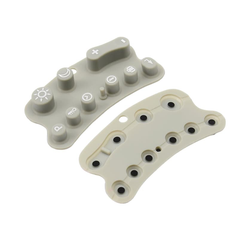
A carbon pillar is co-molded with the silicone dome: conductive compound is loaded into the pillar cavity while the dome is formed, so the pillar and dome cure as one part. The pillar is typically 0.8–2.0 mm in diameter and 0.4–1.2 mm tall, depending on the contact layout. Because conductive compound contains a high filler loading, it is stiffer and more notch-sensitive than the dome material around it — which is precisely where the design trap lies.
Industry descriptions of conductive keypad contacts confirm the standard construction: a molded silicone key with a conductive element under the key that closes a circuit on the PCB. The crack forms at one of three locations: at the pillar-to-dome fillet (bending stress concentration), through the pillar body (shear from off-axis actuation), or at the pillar face (impact against a hard PCB land or an uneven gold-plated pad).
Root Causes of Carbon Pillar Cracking in Silicone Keypads
From field returns and lab testing, carbon pillar cracking in silicone keypads traces back to a small set of repeatable root causes:
1. Over-carbon-loaded compound. Pushing carbon loading to the maximum for low resistance makes the pillar brittle. Material research on carbon-black-filled silicone rubber shows that increasing filler content raises conductivity but degrades elongation and tear strength — the exact properties a pillar needs to survive impact.
2. Sharp fillet geometry. A 90° fillet between pillar and dome concentrates bending stress. A 0.2–0.4 mm radius fillet roughly doubles the impact cycles a pillar survives.
3. PCB land contact over a hard edge. If the PCB pad sits proud of the board surface or has a sharp solder fillet, the pillar face is punched repeatedly against a knife edge during use.
4. Thermal cycling with mismatched shrinkage. The conductive compound and the dome compound shrink differently through the cure cycle; repeated thermal expansion in service works the interface until a micro-crack forms.
5. Gate or flash remnants. A small flash stub left on the pillar face acts as a crack initiator that propagates under normal pressing.
Note the common thread: every root cause is decided at the design or tooling stage, not in the field. That is good news for OEMs, because it means carbon pillar cracking is preventable before the first production run.
Diagnosis: Separating a Cracked Pillar from a Worn Contact
When a thermal camera comes back with a dead function key, the diagnosis path determines whether you fix the product or the design. A cracked pillar behaves differently from a worn contact:
- Check intermittency pattern: a cracked pillar is intermittent at specific press angles (press the key corner vs. the center); a worn contact is consistently high-resistance regardless of angle.
- Measure at low force: a cracked pillar shows wildly unstable readings below the crack-opening threshold.
- Inspect the pillar face: a hairline crack on the face or a missing chip identifies impact damage; a shiny flattened face identifies wear.
- Section the pillar: cross-sectioning under magnification reveals whether the crack initiated at the fillet (bending) or the face (impact) — this tells you which design change to make.
What a Cracked Pillar Looks Like Under Magnification
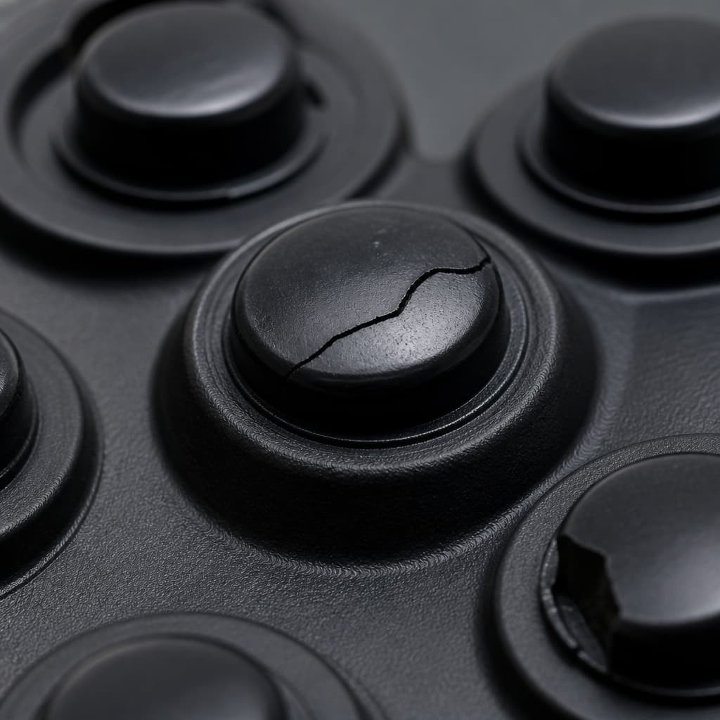
Macro inspection of a failed button typically shows a jagged fracture across the contact element, with the crack propagating from the stressed edge. In the field this crack is invisible to the user — the silicone dome surface stays intact — which is why the failure is reported as "button stopped working" rather than "pillar cracked." The visual diagnosis is the fastest route to the correct root-cause category, and it is the same discipline described in our guide on deep-draw silicone keypad cracking and draw-ratio assessment, where the fracture location identifies the design error.
Case: 400 Thermal Cameras with Intermittent Function Keys
A thermal-imaging OEM contacted us after a distributor returned 400 units with intermittent HOLD and MODE keys. The first diagnosis was the PCB contact plating; the second was the firmware debounce. Both were wrong.
- Field data: failures clustered in units used in outdoor winter work, operated with heavy gloves, and stored in vehicles overnight.
- Lab finding: sectioned pillars from failed units showed face-initiated cracks with a chip pattern matching impact against a raised PCB land. The land height was 0.35 mm above the board surface — above the recommended limit.
- Design changes: pillar fillet radius increased to 0.3 mm, PCB land flattened to board level, and the pillar compound re-formulated to a slightly lower carbon loading with a small elongation sacrifice.
- Result: 500-cycle drop testing at 1 m and 20,000-cycle glove-force actuation produced zero pillar failures in the validation build.
The total engineering time was two weeks; the alternative was reworking 400 units and losing the distribution channel's confidence. For design teams facing this class of problem, the electrical-contact discussion in our PCB assembly troubleshooting guide for conductive contact failure is the natural companion reading.
Designing the Array for Impact Survival
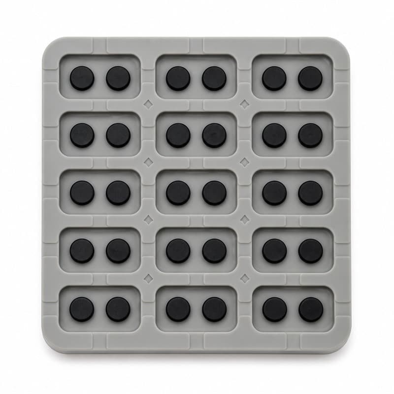
When the contact elements are laid out in a dense grid, each pillar must survive the same abuse. The design rules that emerged from this case — generous fillets, flat PCB lands, and compound balanced for impact rather than minimum resistance — apply to every key in the array, not just the ones that failed. Uniformity across the array is also the first check in why a conductive pill's resistance becomes unstable or too high, because a cracked or chipped pillar reads as a resistance problem before it reads as a mechanical one.
Preventing Carbon Pillar Cracking at the Design and Tooling Stage
Prevention lives in the DFM review, before steel is cut. For any handheld product that will be dropped, gloved, or thermally cycled, put these items on the keypad DFM checklist:
- Pillar fillet radius ≥ 0.2 mm; verify with a drop-test at 1 m on the first-article sample.
- Confirm PCB land coplanarity with the board surface; reject proud lands above 0.2 mm.
- Balance the conductive compound between resistance target and tear strength; require elongation data on the compound certificate.
- Run a combined test: thermal cycling (−20 °C to +60 °C) followed by glove-force actuation, on the pre-production sample.
- Deburr the pillar cavities in the mold; inspect the first 100 pillars for flash remnants.
Carbon pillar cracking is the kind of failure that never shows up in a lab demo and always shows up in the field. Because the silicone surface hides the damage, the only reliable defense is design review plus accelerated testing that mimics the glove, the drop, and the temperature swing.
Sources and further reading:
- Jasper Electronics — Conductive Rubber Keypads with Carbon Pills (construction and application)
- PMC — Effects of Carbon Black on Mechanical Properties of Silicone Rubber (filler loading and tear strength trade-offs)
- LuphiTouch — Electrical Contact Mechanisms in Silicone Rubber Keypads (contact element behavior)
- Rubber-Keypad — What Are Conductive Contacts in Rubber Keypads (contact stability and cycling)
About FromRubber (FrmRubber). FromRubber is a full-process silicone and plastic OEM manufacturer for instrumentation, thermal-imaging, medical, and industrial products. Our engineering team runs drop-test and thermal-cycling validation on every handheld keypad design before tooling, and we document pillar compound and geometry decisions in the DFM report. Send us your keypad drawing or failed sample and we will return a crack-risk review with the recommended compound and fillet changes.