Silicone keypads for smart home device: backlight failure in thin design
Backlight failure in thin silicone keypads for smart home devices is almost never an LED problem. It is an optical-stack tolerance problem: the light path between the LED and the legend has five layers, and each one adds its own variation. On a 0.3 mm-stroke design a 0.05 mm error is enough to produce a bright patch at one key and a dead legend three keys away.
The short answer for design teams: treat the legend as an optical part, not a printed marking. Specify coating thickness with a tolerance, lock the laser parameters per colour and per batch, and move the LED further from the key surface so light mixes before it reaches the character. Everything below explains how those three decisions are made and what they cost when they are skipped.
The five-layer optical stack inside a backlit silicone keypad
A backlit key is built as a stack, and light has to survive every interface in it. Reading the stack in order is the fastest way to find where a design will fail.
- Translucent silicone base — carries the LED light and sets how much of it reaches the legend.
- White reflective ink layer — bounces light back towards the viewer instead of letting it escape downwards.
- Dark topcoat — the unlit appearance of the button; typically black or charcoal.
- Laser-etched legend — removes the dark coat in the shape of the character, exposing the white layer underneath.
- Protective PU or matte topcoat — wear resistance over the etched area.
Every interface scatters or absorbs light. When the stack is compressed into a thin wall, the layers get thinner too, and the scatter-to-transmission ratio changes. That is why a keypad that looked uniform at 1.0 mm wall thickness can show hot spots at 0.6 mm with the same artwork and the same LEDs.
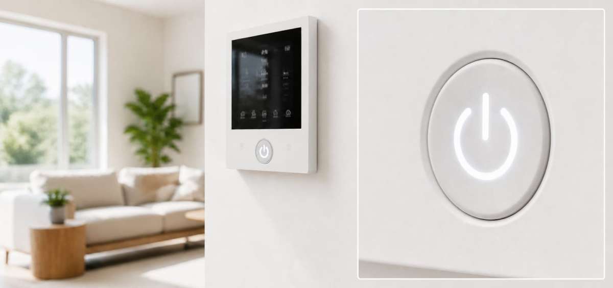
A backlit key is a five-layer optical stack, not a printed symbol on rubber. Uniformity is decided by layer thickness and interface quality.
Where laser etching fails on thin silicone keypads for smart home devices
Laser etching is dominant because it reaches 0.1 mm positional accuracy and lets you move a legend without cutting new tooling. It fails for reasons that are all measurable, and all fixable before tooling is released.
| Failure seen on the line | Root cause | What actually fixes it |
|---|---|---|
| Legends look burned in places, grey in others | Dark topcoat varies by about 0.02 mm across the part | Spray path and fixture control to hold coat thickness inside ±0.01 mm; verify per batch with a film-thickness gauge |
| Light bleeding through the button body | Spray coat too thin; light escapes sideways instead of through the legend | Raise coat thickness and add a light-blocking layer outside the legend zone |
| Fine symbols blurred or closed up | Pad printing cannot hold line widths under about 0.3 mm | Move the artwork to laser etching; check minimum stroke with the etcher before artwork freeze |
| Etched area cannot be corrected | PU topcoat is applied before etching; once etched, the layer cannot be reworked | Etch first, coat after, or accept 100% first-pass yield discipline on the etched panel |
| Hot spot directly above one LED | LED too close to the key surface; no mixing distance | Increase the gap between PCB and key underside, or add a diffuser layer |
None of these are cosmetic. On a smart home panel the legend is the only feedback the user has when the room is dark, and a legend that fades after tens of thousands of presses reads as a product that aged badly.
What a thin-wall backlight project actually requires
Two projects show the same mechanism from opposite ends. In the first, a German medical diagnostic device needed twelve icons 2 mm tall with line widths down to 0.15 mm, backlit, and rated for more than 200,000 actuations.
Standard pad printing closed the small counters. Standard laser etching at the supplier's default settings produced edge charring. The workable route was artwork re-drawn to a 0.1 mm minimum stroke, a dedicated laser recipe for that specific dark coat, and a first-article inspection under the actual backlight rather than under room light. The etched symbols held contrast and passed the 200,000-cycle test without measurable degradation.
The second case, a home automation brand in California, had the opposite problem: light was too strong in one place. The fix was not a stronger LED but a different optical stack — a slightly less translucent compound with light-diffusing additives, a white layer 0.03 mm thicker to improve scattering, 50–80 µm laser-cut micro-channels to guide light across the key face, and a PCB revision that moved the LEDs further from the key surface.
There is no universal laser setting. Line width, coat thickness, pigment load and even the batch of dark ink shift the energy window. A supplier who quotes one recipe for every project is telling you they have not measured theirs.
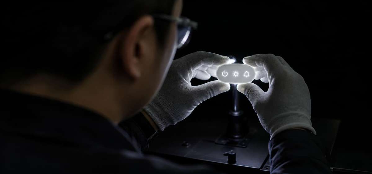
Inspecting legends under the production backlight, at the specified viewing distance, is the only check that predicts what the user will see.
DFM checks to run before tooling is cut
Most backlight failures are already visible in the 2D drawing and the LED layout. These are the checks worth insisting on, in the order that saves the most money.
Optical checks
- Minimum legend stroke versus the etcher's capability — agree the number in writing.
- Distance from LED centre to legend centre, and whether any legend sits directly over an emitter.
- Wall thickness under the legend, and whether the white layer survives that thickness.
- Viewing angle: a legend that reads well head-on can wash out at 45°.
Tolerance checks
- Stroke depth against the tactile target; a thin wall cannot carry a deep tactile bump and a thick coat at once.
- Key-to-key height variation across the panel, which shows up as uneven illumination.
- Gate position, because flow marks change light transmission locally.
Moulded keypads awaiting laser etching and coating. Process order — mould, coat, etch, protect — decides whether a defect is correctable or scrap.
What to send for a backlight keypad quotation
Quotations for silicone keypads for smart home devices go wrong when the supplier is asked to price an unclear optical requirement. Five items remove most of the ambiguity:
- 2D drawing with key pitch, wall thickness, stroke depth and legend stroke width.
- LED layout with emitter positions, viewing angle and drive current.
- Colour targets as Pantone references for the unlit coat, plus the lit colour you are willing to accept.
- Tactile target in grams-force, or a reference product the team considers correct.
- Cycle life and the environment: indoor only, or a bathroom and kitchen panel that sees steam and cleaning agents.
With those five, a DFM review can be specific: which legends will close up, which keys will sit above an emitter, and whether the wall can carry the coat. Without them, every quotation is a guess, and the guess is usually resolved after the mould exists.
Our own workflow runs DFM feedback before tooling and uses quick proofing samples so the backlight is judged on real silicone. The broader process is described under custom silicone rubber keypads, and laser legend capability under laser etching.
Tooling, coating and etching under one roof shortens the loop between a failed light test and a corrected sample.
Questions buyers ask about backlit thin keypads
How thin can a backlit silicone keypad be?
Thin enough for a 0.3 mm stroke is routine. The constraint is not the moulding but the optical stack: below roughly 0.6 mm wall under the legend, the white reflective layer and dark coat compete for space and uniformity becomes hard to hold. Below that, plan for a diffuser layer or accept a tighter LED layout.
Can we keep our existing artwork and just change the manufacturer?
Usually not without a redraw. Artwork built for pad printing often contains strokes under 0.3 mm and small counters that a new process cannot reproduce. A DFM pass on the artwork costs far less than a rejected first article.
Does a thicker white layer always improve brightness?
It improves scattering, not output. Past a point the extra thickness absorbs more than it reflects and the legend dims. The usable window is found by measurement on the actual compound, not by rule of thumb.
Why do legends fade unevenly across one keypad?
Because the coat is uneven, or because some keys sit closer to an emitter and run hotter. Heat accelerates the PU topcoat's wear. Both causes are visible in a film-thickness map and a thermal image before shipment.
Start a backlight keypad project before the mould exists
We review optical stack, legend stroke and LED placement against your drawing, then quote tooling and unit price on a design that can actually be moulded and etched. Laser etching reaches 0.1 mm line width, sample moulds run in 3–5 days, and tooling is in-house.
Send your 2D drawing and LED layout through the custom silicone service process, or review the standard custom silicone rubber keypad range first.