Silicone GPS Tracker Holder Design: How to Balance a Secure Fit with Easy Removal
Two complaints arrive from the same product line, and they sound like opposites. One buyer says the tracker falls out of the silicone holder within a week. Another says the cover has to be prised off with a coin, and the charging port is now scratched. Both are correct. Both come from the same mistake: treating “secure” and “easy to remove” as two ends of one dial instead of two different requirements.
A silicone GPS tracker holder is not tight or loose in the abstract. It is tight in specific places, along specific paths, at specific moments. Once you separate those, the conflict mostly dissolves, and the remaining trade-offs can be chosen deliberately rather than discovered in the field.
The conflict is geometric, not moral
Retention is the work required to move a tracker out of its cavity under the loads of normal use. Removal is the work required to move it out on purpose, with fingers, in one motion. A design fails when those two numbers are not separated: the cavity is sized so the device barely enters, which makes retention excellent and removal a struggle, or it is sized for comfortable entry, which makes removal easy and retention accidental.
The question that resolves this is not “how tight should it be”. It is “when, where and how often does this device leave the holder?” A tracker that stays installed for a season and charges through a port wants high retention and indifferent removal. A tracker that is taken off every night wants a defined release path with a predictable force. Those are different products even if they look alike.
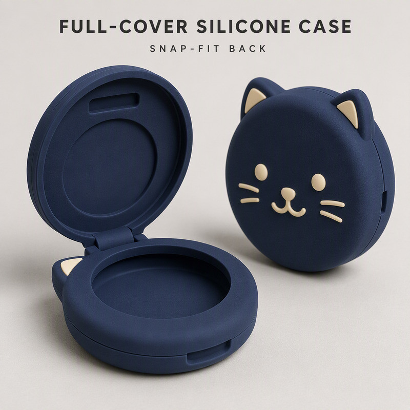
Open and closed views of the same cover show where the two requirements actually live. The cavity and its retaining lip control the tracker; the outer shell and its hinge line control handling. A snap-fit back changes the removal path completely: instead of stretching a rim over the device, the user opens the shell, and the retention force is carried by the latch rather than by elasticity.
That is worth stating plainly, because it reframes the design brief. If you choose a shell with an opening mechanism, you no longer need to solve retention with interference fit, and you can size the cavity for a comfortable drop-in. The trade moves to the latch: engagement depth, opening effort, and wear across cycles.
Split the product into two interfaces before changing anything
Almost every “too tight” or “too loose” complaint is really a complaint about one interface that has been attributed to the other. Diagnose them separately.
Tracker to holder
This interface is defined by cavity length, width and thickness, the corner radii, the depth of any retaining lip, and how much of the device sidewall the cover actually touches. Extraction force is the sum of friction along the contact area and the elastic resistance of the lip. Both rise sharply when the cavity is undersized at the corners, which is why a device that measures correctly can still feel jammed.
Holder to collar
This interface is defined by channel height, channel length, edge contact and the collar’s own compressibility. It has nothing to do with how well the tracker is held. A holder can be impossible to open and still rotate freely on a slick webbing strap. The same mechanics explain why a rubber grommet twists during installation: contact that is uneven on one side becomes rotation.
Fix one interface at a time. Changing hardness to solve collar rotation will also change insertion force, and if both are changed at once you cannot tell which change produced the result.
Five features that decide the balance
1. Cavity clearance
Clearance is the gap between the device and the cavity wall at its tightest point. Too little and the corners act as a press fit; too much and the device moves until a corner loads the lip, which is worse than a small uniform gap because the load is concentrated. The useful measure is not the nominal cavity size but the gap at each corner after molding.
2. Retaining lip geometry
Lip height sets how much material sits over the device face; undercut depth sets how far the lip must be deflected to release; the entry ramp sets how that deflection begins. A tall lip with a square undercut holds well and releases badly. A shorter lip with a generous ramp releases easily and holds less. Most production designs land somewhere between, with a ramp on the entry side and a squarer face on the retaining side.
3. Sidewall thickness
Thin walls flex locally, which lowers insertion force and concentrates strain at the rim root. Thick walls distribute the load and make the part feel rigid in the hand. Neither is universally better; the wall has to suit the removal frequency. A cover opened twice a day should not have the wall section of a cover installed once a year.
4. Hardness and elastic recovery
Hardness is an indentation measurement, not a spring rate [2]. Two compounds at the same durometer can differ in how quickly and completely they return after being stretched. The one that recovers slowly leaves the rim slightly open, and the retention that measured well on day one is gone by week six. Where repeated stretching is expected, compare compression set as well as hardness [3], and treat the pair as the material decision rather than hardness alone.
5. Grip and surface texture
Texture helps a thumb find an edge. It does not compensate for a cavity that is 0.6 mm too large, and it can work against removal by increasing friction on the surfaces the user needs to slide. If the product is opened by hand, put the texture where the fingers go, not across the whole outer face.
Designing for frequent removal
If the device comes out weekly or daily, the removal gesture deserves the same attention as the retention feature. Four things make the difference:
- A place to pull. A molded notch, a raised tab or a visible seam gives the thumb a start point. Without one, users improvise with keys and fingernails, and the damage happens at the rim root.
- A predictable path. The part should release in one direction. If it can be opened from two directions, one of them will be the wrong one, and the rim will be loaded in peel instead of shear.
- Clearance around ports and buttons. An opening that requires the device to be tilted past a charging port will scratch it, and the scratch becomes the complaint even when the fit is correct.
- Edge thickness where fingers load it. Thin edges tear at the point of grip. A slightly thicker grip zone costs a little material and removes a whole failure mode.
Why a holder drifts loose, or becomes impossible
Drift is usually gradual and has more than one cause. The table below separates the common symptoms from the checks that actually distinguish them.
| Symptom | Probable cause | Check that confirms it | Usual correction |
|---|---|---|---|
| Device enters with a click but rattles later | Cavity oversized at the corners, or lip too short to stay engaged | Measure gap at each corner on a molded part; inspect lip contact marks | Revise cavity corner radii; increase lip engagement, not overall tightness |
| Device will not seat without force | Corner radius mismatch or insufficient draft on the cavity wall | Compare device corner radius with cavity; look for drag marks on the sidewalls | Adjust radius and draft; do not soften the compound first |
| Rim tears within weeks | Lip root too thin, or removal happening in peel | Inspect tear origin; check whether users open from a corner | Thicken the root, add a release notch, define a single removal direction |
| Fit was good, now loose | Elastic recovery loss or compression set in the compound | Compare a used part with an unused one from the same batch | Re-evaluate compound recovery; adjust wall section |
| Second batch fits differently | Shrinkage variation, tool wear or changed process parameters | Measure critical dimensions across both batches | Bring critical dimensions under a tolerance class and inspect them [1] |
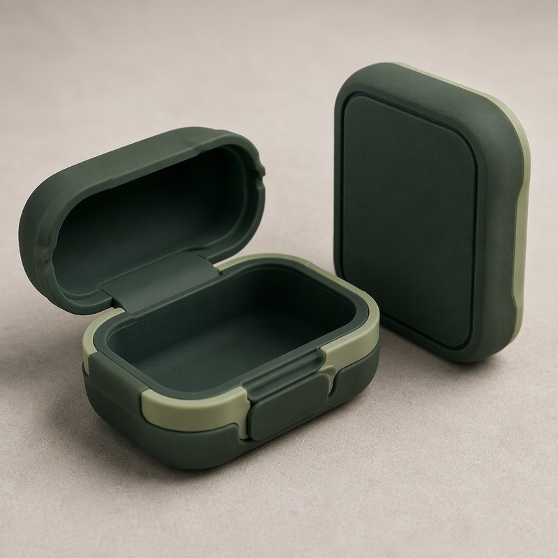
The clamshell above is a useful case because the retaining feature is visible when open. The lip depth can be measured, the cavity floor can be checked for flatness, and the hinge can be inspected for flash. On a closed sleeve, none of that is accessible, and a fit problem has to be inferred from contact marks and insertion feel.
That is one reason a covered design is easier to specify: the features that control retention can be put on a drawing and measured on a part. It is also why the hinge and latch need their own inspection points. A latch that engages 1.2 mm on the prototype and 0.8 mm in production will pass a visual check and fail in a pocket.
Moldability limits what you can promise
A deep undercut is easy to draw and hard to mold. Every millimeter of undercut has to be released, either by stretching the silicone or by a tooling feature, and both have consequences. Stretching at ejection puts strain exactly where the rim is thinnest; a sliding core adds tooling cost and a parting line in a place that may be visible.
Thin retaining lips are the other recurring problem. A lip that measures 0.6 mm in CAD may mold at 0.5 mm at the root, which is where it will tear. Draft on the cavity wall, a generous root radius and a sensible parting line do more for durability than a harder compound. Flash matters too: a thin fin on the cavity floor prevents the device from seating fully, and the symptom looks like an oversized cavity rather than a molding defect.
The practical rule is to review moldability before appearance. A parting line that runs across the outer face may be unacceptable for a branded product, but moving it to an edge can trap air or create a step at the seal surface. That trade belongs in the design review, not in a post-sample complaint.
Test retention with a method, not an opinion
“Feels secure” is not a specification. A workable evaluation for a small silicone holder looks like this:
- Define the direction of removal and pull in that direction only, so results are comparable between samples.
- Record the force at first movement, not just the maximum. The first movement is what the user feels when the device starts to release.
- Cycle the part a defined number of times, then repeat the measurement on the same sample.
- Repeat on a collar, not only on a bench, and include a bend around a form that approximates a neck.
- Inspect the rim root, the cavity corners and the latch after cycling, and record whitening or deformation.
Acceptance limits have to be agreed for the specific product. A number borrowed from another project is not a specification, and an informal pull test is not a certification. What matters is that the buyer and the molder measure the same thing the same way, and that the revision can be judged against it.
In use, the holder also has to survive handling that no bench test reproduces. A cat leaning against a windowsill puts a slow, steady load on the collar and the cover; a dog shaking off water puts a short, violent one. The first tests creep and recovery, the second tests the latch or the lip under impact. If the design only addresses one of those, the field complaint will come from the other.
This is also where wall thickness shows its second face. A thicker wall resists impact better and feels more substantial, but it reduces the local flexibility that lets a rim release. On a small cover, one millimeter of extra wall can turn a two-finger opening into a two-hand operation.

What to confirm before sampling
Most revision loops are caused by information that was never exchanged. Before a sample is made, confirm the device sample or CAD revision, the collar samples at both ends of the range, how often the device will be removed and by whom, which surfaces must not be scratched, the material and hardness if already chosen, and the acceptance method for fit and force. If the product carries a brand, confirm where the logo sits relative to the opening, because moving a logo after tooling is a mold change.
None of this makes a silicone holder waterproof or shockproof. It holds a device and it releases when asked to; those are the two promises the geometry can keep.
FromRubber, the export brand of Dongguan Bohao Electronic Technology Co., Ltd., works on custom silicone covers and holders for pet product teams in Dongguan, Guangdong, and reviews retention and removal as separate requirements before tooling rather than treating them as one setting. Drawings, device samples and collar measurements can be sent to nani@fromrubber.com or karl@fromrubber.com, and we are on WeChat and WhatsApp at +86 186 7621 0913. Background on how we approach molded parts is in our silicone product technology section, and application notes are under silicone product applications.
Questions that come up in review
Should a silicone tracker holder fit tightly?
It should fit tightly where retention is needed and comfortably where fingers need access. A uniform tightness across the whole part is what makes removal difficult. Local control is the point.
Does softer silicone make removal easier?
Usually, and it also makes retention less predictable. Soft compounds deflect more under load, so the lip can roll instead of staying seated. If removal is the problem, look at the ramp and the grip area before changing hardness.
Can a holder stay secure without a rigid buckle?
Yes, if the geometry does the work: a defined lip engagement, a cavity that matches the corners, and enough contact area on the collar. Rigid components solve specific problems, such as a latch that must not creep, and add assembly steps.
Why does a later batch fit differently?
Shrinkage, tool wear, compound variation and process drift all move dimensions. Parts that were measured only at the prototype stage have no baseline, so the difference appears as a fit complaint rather than a dimensional one.
When should the mold be revised instead of the material?
When the failure follows geometry: a lip that is visibly too short, a cavity corner that does not match, a channel that binds on one edge. Material changes are the right answer when the part deforms permanently or recovers too slowly.
The two requirements are separate, so specify them separately
Retention and removal are not a single setting to be tuned by feel. They are two behaviors produced by different features, measured by different methods, and often owned by different people in the same project. A drawing that states both, in measurable terms, removes most of the argument that otherwise happens after the first shipment.