Silicone Case Mold Parting Line Design: The Complete Guide to Flawless Finish
Why Parting Line Design Matters More Than You Think
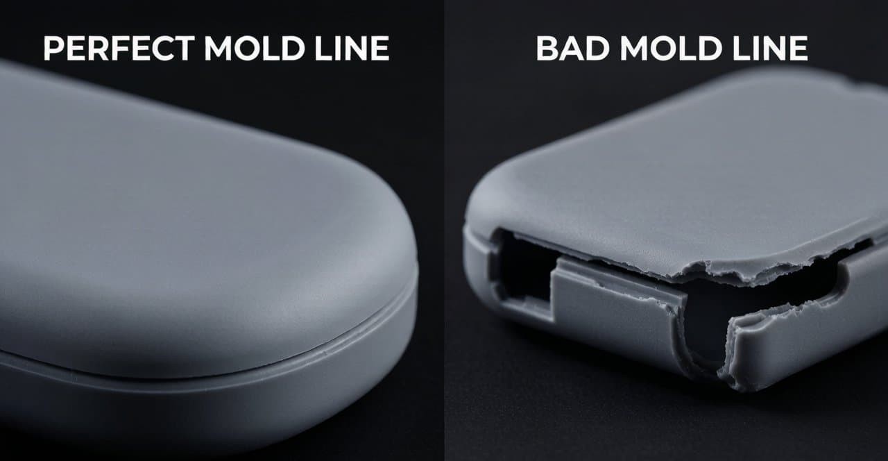
If you have ever received a silicone protective case with a rough edge that feels scratchy against your fingers, or noticed a thin film of excess silicone along the seam — you have seen the consequences of poor parting line design. The parting line is where the two halves of a mold meet, and on every silicone product, it leaves either a subtle witness mark or visible flash. You cannot eliminate it. But you can choose exactly where it goes — and that choice determines your product's cosmetic quality, manufacturing yield, and production cost.
For brand owners, procurement managers, and industrial designers sourcing custom silicone case molds, understanding parting line strategy is the single most important step before committing to tooling. A poorly placed parting line can trigger expensive T2 and T3 mold revisions, scrap thousands of parts, and delay your product launch by weeks. A well-designed one, by contrast, produces a near-invisible seam, zero post-processing, and yield rates above 98%.
At FromRubber, we have engineered over 1,200 custom silicone molds for global electronics brands. This guide distills our parting line design philosophy — built on 15+ years of precision manufacturing — into actionable knowledge you can apply to your next project.
The "Hide Inside, Avoid Visible Surfaces" Principle
The golden rule of silicone case mold parting line design is deceptively simple: place the parting line where the user will never see or feel it. In practice, this means positioning it along the natural geometric transitions of the product — the inner bottom radius, the inside edges of button cutouts, the corners where sidewalls meet the base.
Here are the ideal locations for a silicone protective case:
- Along the inner bottom fillet transition — The curve where the sidewall meets the base interior is naturally shadowed and out of sight.
- Inside edges of port openings and button cutouts — These functional openings already have defined edges that disguise the witness line.
- Natural transitions between sidewalls and bottom surfaces — Any geometric break in the product's surface provides a "free" camouflage zone.
Locations to avoid at all costs:
- Across a flat, high-gloss cosmetic surface — flash and witness marks become highly visible
- Through sealing surfaces — flash on a sealing face causes functional failure
- Across embossed textures, logos, or patterns — the parting line interrupts pattern continuity
Parting Surface Accuracy: The 0.01mm Standard
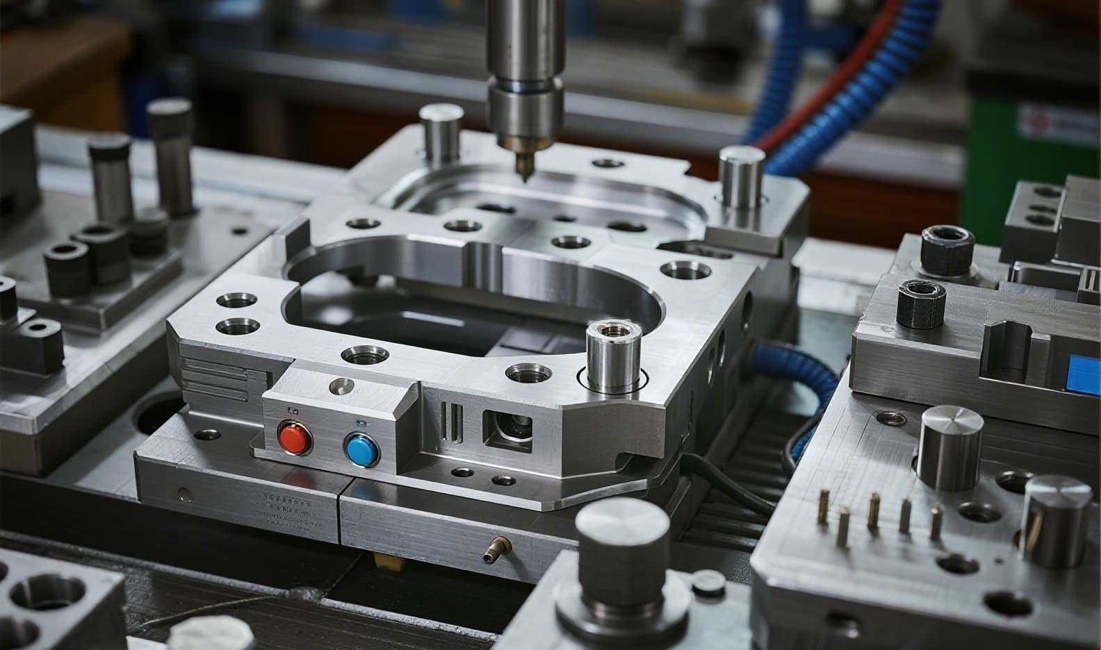
The accuracy of the parting surface — where the two mold halves seal against each other — directly determines flash thickness. In precision silicone injection molding, the industry benchmark is a parting surface gap (FL) of 0.01–0.02mm, producing flash of 0.05mm or less. Achieving this requires a chain of precision:
- CNC Machining Tolerance ≤ 0.005mm — The mold halves must be cut on high-speed CNC or mirror EDM equipment with micron-level repeatability. Standard machining (±0.05mm) produces visibly inconsistent seams.
- Flatness Verification — Every parting surface is checked with a CMM or straightedge and feeler gauge. Target flatness: ≤ 0.01mm across the entire surface.
- Prussian Blue Contact Test — During the trial run, engineers apply Prussian blue dye to one mold half, close under pressure, and inspect the transfer pattern. Uniform coverage means perfect contact; patchy transfer indicates high spots that need correction.
- Surface Hardening — TiN or DLC coating on the parting surface raises hardness to HV 2000+, preventing wear over tens of thousands of cycles.
How Parting Line Location Impacts Flash Control
Flash — the thin excess silicone that bleeds out along the parting line — is the most visible symptom of poor parting line design. But flash is rarely a single-cause problem. It is almost always the result of interacting factors:
| Root Cause | Symptom | Solution |
|---|---|---|
| Insufficient clamping force | Uniform flash around entire parting surface | Increase tonnage; verify with clamp-force calculation |
| Worn or damaged parting surface | Localized flash in one area | Regrind surface; recheck flatness |
| Oversized vent grooves (> 0.02mm) | Flash at vent locations only | Reduce vent depth to 0.01–0.015mm |
| Low-viscosity LSR material | Extremely thin, widespread flash | Select higher-viscosity grade; lower mold temperature |
| Excessive mold temperature | Flash worsens as temperature rises | Stabilize at optimal cure temperature (±3°C) |
At FromRubber, we apply a systematic flash-control protocol: design geometry that minimizes flash impact + precision tooling with tight shut-off + in-process inspection that catches deviation before scrap accumulates. This three-layer approach consistently holds flash below 0.03mm for premium-brand cases.
Real-World Case: Bluetooth Earbuds Charging Case Cover
Challenge: 15% Rejection Rate from Visible Parting Line Flash
A leading audio brand approached us with a Bluetooth earbuds charging case cover that had the original parting line running through the middle of the front sidewall. The result: 15% of units required manual flash trimming, adding $0.32 per unit in labor costs. More critically, the hand-trimmed cases had inconsistent edge quality — some were under-trimmed (still scratchy), others over-trimmed (thin wall, loose fit). Customer complaints were rising.
Solution: Relocate Parting Line + Cryogenic Deflashing
Our engineering team redesigned the parting line, moving it from the visible sidewall to the inner R-angle at the base — a location completely hidden from the user's view. We also:
- Reduced the parting surface gap from 0.04mm to 0.012mm through precision re-grinding
- Added a 0.03mm × 6mm overflow groove adjacent to the parting line to trap minimal flash
- Introduced cryogenic deflashing as a secondary pass (only 0.2s per part, no hand labor)
Result: Flash Reduced to 0.03mm, Zero Post-Processing, 98% Yield
The new design eliminated the manual trimming step entirely. Flash thickness dropped from 0.15mm to 0.03mm — below the visible threshold for end users. Yield improved from 85% to 98%, and the brand saved $0.32/unit in labor while eliminating a major source of quality variation.
Mold Flow Simulation: Validate Before Cutting Steel
Before any steel is cut, FromRubber runs Moldflow or Moldex3D simulation on every new silicone case mold design. Simulation reveals:
- Filling pattern — Whether the silicone reaches all cavity extremities before curing begins
- Weld line prediction — Where flow fronts meet (these become weak points in thin-wall sections)
- Air trap identification — Locations where gas gets trapped, requiring venting adjustments
- Pressure distribution at the parting line — Uneven pressure causes the mold to "breathe," producing flash
Our typical simulation workflow takes 2–3 days and eliminates 90%+ of parting-line-related defects before the first trial shot. It is the single highest-ROI investment in the mold development cycle.
The Secondary Finishing Toolkit
Even with optimal parting line placement, some silicone products — particularly ultra-thin cases under 0.6mm wall thickness — may require post-molding finishing. At FromRubber, we maintain a graded approach to secondary operations:
| Method | Flash Removed | Cycle Time | Best For |
|---|---|---|---|
| Cryogenic deflashing (-100°C) | ≤ 0.08mm | 0.2s/part | Thin, flexible silicone cases — high volume |
| Automated robotic trimming | ≤ 0.15mm | 1.5s/part | Medium volumes, consistent geometry |
| Manual inspection + micro-trim | Any thickness | 5–10s/part | Low-volume premium samples, first articles |
| No finishing needed (flash ≤ 0.03mm) | None | Zero | Production-optimized molds with precision parting surfaces |
The goal is always to eliminate post-processing entirely by getting the parting line design right in the DFM phase. Our track record: 72% of new silicone case molds produce parts with flash ≤ 0.03mm on the first trial, requiring zero secondary finishing.
How to Choose a Manufacturer for Precision Parting Lines
The quality of your silicone case's parting line ultimately reflects the capability of your manufacturing partner. Here is what to look for when evaluating a custom silicone mold manufacturer:
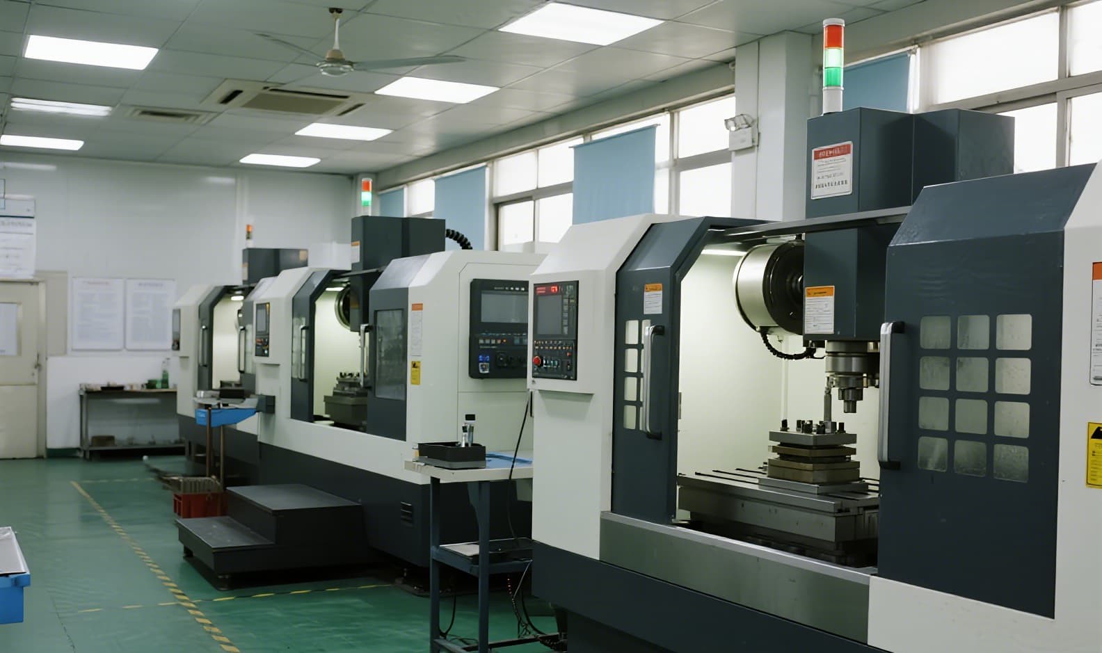
- In-House Tooling — A manufacturer that designs and cuts its own molds controls the entire tolerance chain. Outsourced tooling introduces communication gaps and quality variability.
- CNC + EDM Capability — Look for 5-axis high-speed CNC (Röders or equivalent) and mirror EDM capability. These are prerequisite for parting surface flatness ≤ 0.01mm.
- DFM as a Standard Service — The manufacturer should provide a free DFM analysis before you commit to tooling, including a parting line recommendation with visual markup on your 3D model.
- Integrated Silicone Molding — Tooling + production under one roof ensures that any parting line issue discovered during trial runs can be corrected immediately without cross-vendor coordination.
- ISO 9001 / IATF 16949 Certification — Certifiable quality management systems prove that the facility maintains equipment calibration, material traceability, and process control documentation.
At FromRubber, we check all five boxes. With 15+ years of precision silicone molding experience, a 3,200m² dedicated facility, and over 1,200 molds delivered, we are the partner of choice for brands that refuse to compromise on cosmetic quality.
FromRubber's Parting Line Quality Commitment
When you work with FromRubber, here is exactly what you get for parting line quality:
- Guaranteed flash ≤ 0.05mm on all production molds after T1 optimization
- Premium-grade flash ≤ 0.02mm available with cryogenic deflashing and hardened parting surfaces
- Free DFM analysis with parting line markup within 3 business days of receiving your 3D model
- Full dimensional report (CMM + 3D blue-light scanning) for every first article
- CPK ≥ 1.33 on critical fit dimensions before mass production sign-off
Ready to Engineer Your Silicone Case Mold?
Get a free DFM analysis with parting line recommendation within 3 business days. Send us your 3D model and we will show you exactly how to achieve a flawless finish.
👉Send Your Design for Free DFM Review