Precision Silicone Shrinkage Compensation: The Complete Guide to Getting Mold Dimensions Right
What Is Silicone Shrinkage and Why Does It Matter?
Silicone shrinkage is the dimensional reduction that occurs when a silicone part cools from its curing temperature down to room temperature. It sounds simple — but in practice, getting it wrong is the single most common reason custom silicone molds fail on the first try.
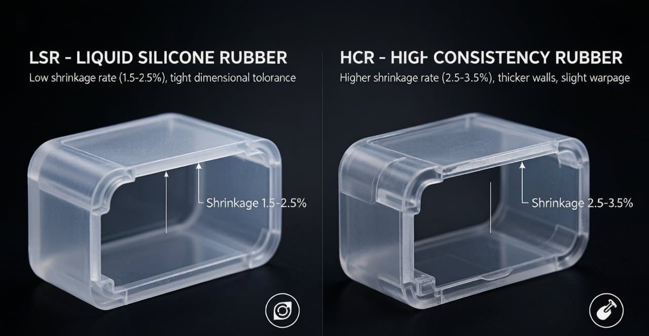
For protective cases molded from Liquid Silicone Rubber (LSR), the typical linear shrinkage ranges from 2.5% to 3.5%. For High Consistency Rubber (HCR), the range is 1.5% to 2.5%. A 3% error on a 100mm phone case means the finished part is 3mm too small — enough to make assembly impossible. At FromRubber, we treat shrinkage compensation as the foundation of every mold design, not an afterthought.
Why a 1% miscalculation destroys your tolerance budget: If your case requires a ±0.10mm fit tolerance and your shrinkage assumption is off by just 0.3%, you have already consumed 3x your entire tolerance window before the first shot is even molded. Precision starts with the shrinkage number.
LSR vs. HCR: How Shrinkage Behavior Differs by Material
Not all silicone shrinks the same way. Understanding the fundamental difference between LSR and HCR shrinkage behavior is the first step toward building a reliable compensation strategy.
LSR Shrinkage: The Dual-Phase Challenge
LSR behaves differently from thermoplastics: it actually expands slightly inside the hot mold during curing (the cavity typically fills to ~98-99% volume, with the material thermal expansion completing the fill). The real shrinkage happens after demolding, as the part cools to room temperature — typically a 2.5-3.0% linear contraction. An additional 0.5-0.7% can occur during post-curing. This dual-phase behavior makes fixed-ratio compensation unreliable for precision parts.
HCR Shrinkage: More Predictable but Still Demanding
HCR (compression-molded solid silicone) generally shows lower and more consistent shrinkage, typically 1.5-2.5%. However, HCR is more sensitive to material loading weight, mold pressure, and cure time — operator-dependent factors that introduce batch-to-batch variation if not carefully controlled.
| Parameter | LSR | HCR |
|---|---|---|
| Typical Shrinkage Range | 2.5% – 3.5% | 1.5% – 2.5% |
| Shrinkage Mechanism | Expands in mold, shrinks on cooling + post-cure | Shrinks uniformly during vulcanization and cooling |
| Post-Cure Effect | +0.5% – 0.7% additional shrinkage | +0.2% – 0.4% additional shrinkage |
| Best Suited For | Thin-wall cases, complex geometries, high volume | Thicker parts, lower volume, simpler shapes |
| Typical Tolerance (ISO 3302 M2) | ±0.08 – 0.15 mm | ±0.10 – 0.20 mm |
7 Critical Factors That Influence Silicone Shrinkage
Shrinkage is not a fixed material property — it is the result of a complex interaction between material chemistry, mold design, and process parameters. Based on extensive testing at FromRubber precision molding facility, here are the factors that matter most:
- Durometer (Hardness): Higher Shore A values produce less shrinkage. A 70 Shore A silicone may shrink 0.5-1.0% less than a 30 Shore A grade of the same base polymer.
- Curing Temperature: Every 10°C rise in mold temperature increases shrinkage by approximately 0.1-0.2%. Temperature control within ±3°C is essential.
- Cavity Pressure: Higher injection and packing pressure compacts the material more uniformly. Ideal range is 60-100 MPa for most LSR applications.
- Filler Content: Silicone compounds with silica fillers shrink less than unfilled or transparent grades. Heavily filled compounds can reduce shrinkage by 0.5-1.0%.
- Wall Thickness Variation: Uneven wall thickness creates differential curing rates. Keep adjacent wall thickness ratios ≤ 2:1.
- Flow Direction and Gate Position: Shrinkage is anisotropic — material shrinks differently along the flow direction versus perpendicular to it.
- Post-Curing Conditions: Post-curing at 150-200°C for 1-4 hours causes additional crosslinking, resulting in 0.2-0.7% extra shrinkage.
FromRubber insight: Different silicone brands — Dow, Wacker, Shin-Etsu — can have shrinkage coefficient differences of up to 0.3% even at the same hardness rating. Always test with the exact production-grade material before cutting steel.
The Engineering Behind Shrinkage Compensation
The industry has evolved through three generations of shrinkage compensation methods. Understanding where your supplier operates tells you a lot about the dimensional quality you can expect.
Level 1: Fixed-Ratio Compensation (Common but Risky)
Multiply all cavity dimensions by a single factor (e.g., 1.03 for 3% shrinkage). Works only for simple, regular parts with uniform wall thickness.
Level 2: Piecewise Linear Compensation (Better for Industrial Parts)
Different shrinkage rates applied to different geometric zones. Achieves dimensional accuracy within ±0.10%.
Level 3: Nonlinear Dynamic Compensation (Precision Standard)
The gold standard. Combines cavity pressure, curing temperature, and shear direction data. CNC five-axis machining applies pre-compensation. Achieves dimensional error within ±0.05%.
FromRubber uses Level 3 compensation for all precision silicone case molds. Our engineering team builds a material-specific shrinkage model for every project.
Step-by-Step: FromRubber Shrinkage Compensation Workflow
Precision shrinkage control spans the entire mold development lifecycle. Here is how we do it at FromRubber:
- DFM Review and Material Confirmation: Before any steel is cut, we review the 3D model and lock in the exact silicone grade.
- Shrinkage Test Coupons (ASTM D955): Mold test coupons using the actual production batch and measure real shrinkage.
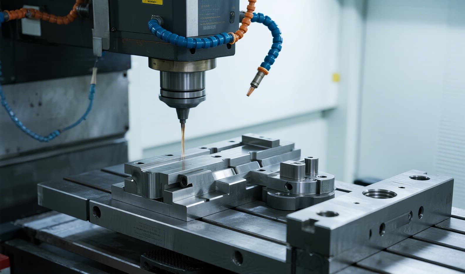
- Mold Cavity Pre-Compensation: Apply nonlinear dynamic compensation to the cavity CAD model before machining.
- T0 Trial and 3D Scanning: First-shot parts measured using blue-light 3D scanning with ±0.005mm accuracy.
- Iterative Correction (T1, T2): Targeted cavity adjustments using EDM or micro-machining.
- CPK Validation and Production Release: All critical dimensions achieve CPK ≥ 1.33 before production release.
Real-World Case Study: Fixing a 0.35mm Fit Failure
AirPods Pro Silicone Case — Undersized by 0.35mm
The Problem: A customer ordered custom AirPods Pro cases molded in 40 Shore A clear silicone. The first mold used a generic 2.2% shrinkage factor. Cases were 0.35mm undersized — earbuds would not fully seat.
Root Cause: Actual shrinkage measured at 3.1% — nearly a full percentage point above the assumed value.
The Fix: Recalculated cavity compensation to 3.0%, applied +0.10mm positive tolerance, installed thermocouple monitoring within ±3°C.
This case illustrates why FromRubber standard practice requires material pre-testing from the actual production batch before finalizing mold cavity dimensions.
Quality Control: How We Verify Dimensional Accuracy
| Inspection Stage | Equipment | Accuracy | Frequency |
|---|---|---|---|
| First Article Inspection | CMM | ±0.002 mm | Every new mold |
| Full Surface Scan | Blue-light 3D scanner | ±0.005 mm | T0, T1, T2 trials |
| In-Process Sampling | Vision measurement | ±0.010 mm | Every 100 units |
| Color / Hardness | Spectrophotometer + durometer | ΔE ±0.05 / ±1 Shore A | Per batch |
| CPK Monitoring | SPC control charts | Target CPK ≥ 1.33 | Continuous |
Our commitment: Every FromRubber silicone case mold ships with a complete dimensional validation report — CMM data, 3D scan color maps, and CPK analysis.
Common Silicone Shrinkage Myths — Debunked
Myth 1: "All silicone shrinks at the same rate." — False. Different brands and batches can vary by 0.3% or more.
Myth 2: "Just scale the whole 3D model by the shrinkage percentage." — Anisotropic shrinkage means X, Y, Z often need different compensation factors.
Myth 3: "Post-curing does not affect dimensions." — Post-curing can add 0.2-0.7% additional shrinkage.
Myth 4: "Harder silicone always shrinks less." — Filler content and curing system can override the hardness-shrinkage relationship.
Get Your First-Shot-Right Guarantee
Send your 3D model to FromRubber for a free DFM analysis and material-specific shrinkage evaluation.
Request Free DFM AnalysisReceive a dimensional feasibility report within 3 business days