How to Design Megaphone Silicone Buttons for Better Assembly Fit?
A megaphone keypad that looks right on the bench can still stop a production line. The part is the correct shape, the buttons press, and the first assembly goes together. Then the fitters report that the keypad has to be stretched over a rib, that one corner will not stay down, or that the talk button binds once the front housing is screwed shut. None of these are cosmetic complaints, and none of them are solved by a new compound.
Assembly fit in megaphone silicone buttons is decided by three interfaces that are usually drawn by three different people: the keypad's outer profile and locating features, the plastic housing's pocket and openings, and the PCB's switch positions. A keypad that meets its own drawing can still fail if those interfaces are not dimensioned as one stack or if the assembly sequence was never tested. Appearance and pressing feel are separate acceptance criteria, and neither one proves fit.
What Causes Poor Assembly Fit in Megaphone Silicone Buttons?
Megaphones are a difficult fit case because the front panel is small, the wall is thin, and the keypad is often clamped by the same screws that hold the housing together. The silicone part sits between two rigid parts, and any dimensional mismatch is transferred into the keypad rather than absorbed by the housing.
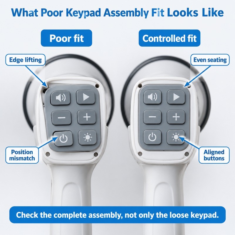
The first cause is the outer profile. A keypad that is slightly oversize will not drop into the pocket, so the fitter stretches it and the frame stays distorted. A keypad that is slightly undersize seats easily but can shift, and the caps drift off their openings.
The second cause is button position. The cap centres must match the housing openings and the PCB pads at the same time. If either the opening pattern or the pad pattern was changed after the keypad layout was fixed, the part will fit mechanically and fail electrically, or the reverse.
Incorrect Outer Dimensions Make the Keypad Difficult to Install
The outer profile is not one dimension. It includes the overall length and width, the corner radii, the location features and the thickness of the frame that is clamped. A keypad can be correct in length and width and still fail because a corner radius is tighter than the housing pocket, which forces the fitter to fold the corner.
The frame thickness matters as much as the outline. If the frame is thicker than the gap between the housing and the internal support, the housing will not close without force, and the force goes into compressing the frame and pre-loading the buttons. If it is thinner, the keypad is loose and can move when operated.
Misaligned Buttons Can Interfere With the Housing Openings
Each cap needs clearance in its opening across the full range of positions allowed by the tolerances. When a cap is offset, one side of the cap rubs the plastic and the other side has a visible gap. The rubbing side feels heavier and returns more slowly, which is often reported as a material problem.
Because the caps are molded as one sheet, a single offset in the keypad affects every button by the same amount. If one button binds and the rest are free, the cause is more likely a local opening dimension or a warped housing than the keypad layout.
Poor Retention Design Can Cause the Keypad to Move After Assembly
Retention has to resist two loads: the push of the user's thumb, which tries to move the cap sideways, and the pull of the housing, which tries to lift the frame. A keypad held only by clamping at the edges can slide in the middle of a large panel, and the caps drift out of alignment over time.
Locating features solve this without adding compression. A small rib entering a groove, or a tab entering a slot, fixes the keypad in the plane of the panel and lets the clamp do only the job of holding it flat.
How Should Button Dimensions Be Designed for Better Assembly Fit?
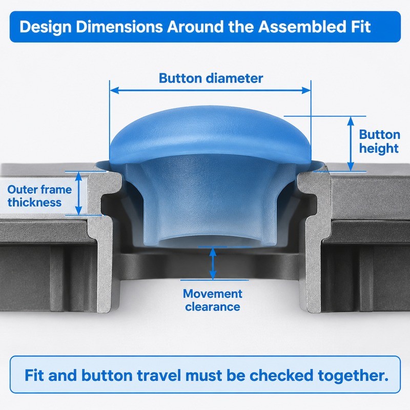
Button dimensions should be set from the assembled condition backwards. Start with the opening in the plastic, the height of the PCB and the required travel, then derive the cap diameter, cap height and frame thickness that satisfy all three.
Cap diameter is bounded by the opening and by the spacing to the next cap. Cap height is bounded by the opening depth and by how much the button should protrude. Frame thickness is bounded by the clamp gap and by the need to keep the caps clear of the opening walls.
Working from the assembly also exposes conflicts early. A cap that is large enough for a gloved thumb may not leave room for the opening wall; a frame that is thick enough to seal may hold the caps down. These are design decisions, and they are much cheaper to make on a drawing.
Match Button Height and Diameter With the Housing Openings
A cap that protrudes too far is easy to find but exposed to knocks, and it can be pressed by the device's own carry strap or by the hand that holds it. A cap that sits below the panel is protected but hard to locate, especially with a glove. The useful compromise is usually a small, consistent protrusion on the operating keys and a flush surface on the setup keys.
Diameter should follow the finger, then be checked against the opening wall. The wall between adjacent openings is a plastic feature with its own minimum thickness, and that minimum often sets the real limit on cap size in a compact panel.
Control the Outer Frame Thickness and Overall Keypad Profile
The frame is the part of the keypad that is clamped, located and seen. Its thickness should be specified at the clamp line, not as an average, because that is where the compression happens. Its width should be enough to carry the locating features and to seal, and no wider than necessary.
The overall profile includes any step between the frame and the button field. A step is useful because it lets the caps sit at the right height without making the whole keypad thick, but it also creates a thin transition that can tear during demolding if the radius is too tight.
Leave Enough Clearance for Independent Button Movement
Clearance around the cap is not only a fit allowance; it is part of the button's spring system. If the cap touches the opening wall, the wall of the button is effectively constrained on one side, which raises force and slows return. The clearance has to remain positive at the worst case, which means accounting for the keypad molding tolerance, the housing opening tolerance and the positional tolerance between them.
A practical check on the assembled sample is to press each cap toward each side of its opening and feel for contact. A cap that binds in one direction but not the other indicates a positional offset rather than a diameter problem.
| Stage | Sample type | What it proves | What it cannot prove |
|---|---|---|---|
| Drawing review | 2D and 3D models | Interfaces are dimensioned against the same stack | Real molding variation, warpage, handling |
| Prototype tool | Single cavity or soft tool sample | Geometry can be molded and the caps can be positioned | Multi-cavity consistency, production trimming |
| First article | Parts from every cavity | Cavity-to-cavity dimensional spread is known | Long-run drift, tool wear, operator variation |
| Pilot assembly | Production parts in production housings | The assembly sequence works at line speed | Field conditions, temperature extremes, service handling |
| Production | Routine sampling | Critical dimensions stay inside limits over time | Anything that was never defined as a critical dimension |
Which Retaining Structures Help Megaphone Silicone Buttons Stay in Position?
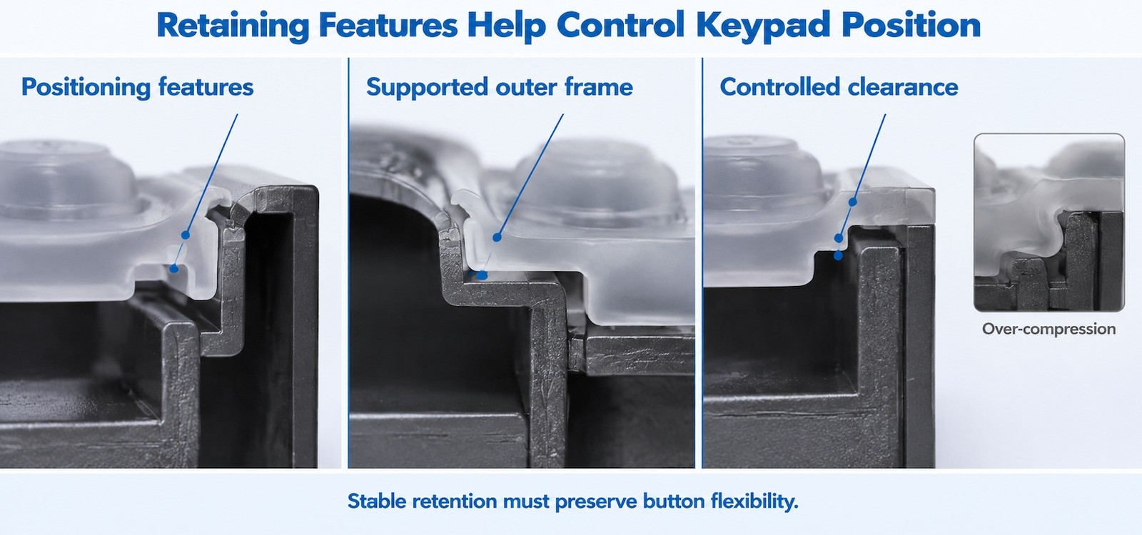
Retention should locate the keypad without compressing it. The most reliable arrangements combine a positive location feature with a light, continuous clamp.
Use Positioning Features to Control Keypad Alignment
Ribs, tabs and grooves fix the keypad in the plane of the panel. They should be designed with lead-in chamfers so the part can be installed without force, and with enough clearance that a small molding variation does not prevent assembly.
The features also have to survive demolding. A rib that is too tall relative to its base will tear when the part is stripped, and the tear will be on the edge that the customer sees. Rounded, shallow features are more robust and locate just as well.
Design the Outer Silicone Frame to Support Assembly
The frame carries the clamp load, the locating features and the seal, and it also has to remain flat. A frame with an uneven section will bow between the clamps, and the caps in the bowed region will sit lower than the others.
Where a seal is required, the frame needs a dedicated sealing bead rather than a thicker flat section. A bead concentrates the compression where it is needed and leaves the rest of the frame free to sit flat. The waterproof keypad construction is an example of separating the seal from the button field.
Avoid Excessive Interference Between Silicone and Plastic Parts
Interference is sometimes specified deliberately, on the assumption that silicone will compress and seal. That works for a gasket; it does not work for a keypad, because the compression is transmitted through the frame into the caps. The result is a panel where every button is partly pressed before the user touches it.
The sign of this in the field is a keypad that feels acceptable when the housing is open and heavy once the screws are tightened. If tightening the housing changes the button feel, the frame is being over-compressed and the clamp design needs review.
How Does Mold Design Affect the Assembly Fit of Silicone Buttons?
The mold decides how closely the produced part matches the drawing, and where the unavoidable variation lands. Two decisions matter most: where the parting line sits, and how the cavities are balanced.
Mold Dimensions Determine the Accuracy of Keypad Features
Cap positions, frame width and locating features are all cut into the cavity, so their accuracy depends on the tool build. The critical dimensions should be identified before the tool is made, the tool should be dimensioned to the middle of the tolerance rather than to nominal so that wear moves the part toward the limit rather than past it, and the first article should be measured against the tolerance classes in ISO 3302-1.
Shrinkage is part of this. Silicone shrinks during cure, and the amount depends on the compound and the section. A tool cut to nominal without shrinkage compensation will produce a keypad that is consistently small, and every downstream dimension will be offset in the same direction.
Parting Lines and Flash Can Affect Installation
The parting line should be placed where flash can be removed cleanly and where any residual ridge will not rub in the housing. On a keypad, the worst position is across the cap side wall or at the base of the button, where a ridge changes the clearance and the feel.
Flash on the outer frame is equally damaging because it changes the effective outline. A thin film of flash around the frame can be enough to make the keypad tight in the pocket, and it is often invisible until the part is assembled. The notes on keypad flash cover the molding causes in more detail.
Uneven Molding Dimensions Can Create Inconsistent Assembly Results
In a multi-cavity tool, each cavity has its own flow path and its own heat history. The differences are small in absolute terms and significant when the available clearance is small. Measuring one part from the middle cavity and shipping the rest is how a keypad passes first article and fails at assembly.
First-article inspection should include parts from every cavity, measured at the same points, with the results recorded per cavity. That record is also what makes it possible to diagnose a later problem, because it shows whether a drifting dimension started in one cavity or across the tool.
How Can Manufacturers Verify Assembly Fit Before Mass Production?
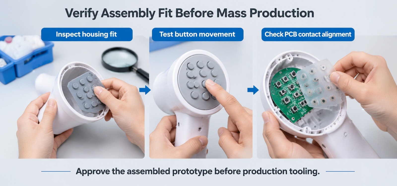
Verification has to use production housings, production PCBs and the production assembly sequence. A keypad tested on a bench with a loose PCB proves almost nothing about fit.
Check the Keypad Against the Actual Plastic Housing
Install the keypad into a production housing and look at the edge all the way around before closing anything. Lift, fold, gaps and visible distortion should be corrected at this stage, not accepted as cosmetic. Then close the housing and re-check, because clamping changes the shape of the frame.
Check the locating features by trying to move the keypad in the plane of the panel with a fingertip. It should not slide. If it does, the location is being provided only by friction, and it will change as the parts wear.
Test Button Movement After the Keypad Is Installed
Press every button, one at a time, in the closed housing. Each should move freely and return fully. Then press each button toward each side of its opening to check for binding. A button that binds in one direction indicates a positional offset; one that binds in all directions indicates a cap diameter or opening size problem.
Check the buttons adjacent to the one being pressed. Any visible dip means the web is coupling the keys, which may be acceptable on a wide panel and unacceptable on a compact one.
Verify PCB Alignment and Electrical Contact
With the unit assembled, confirm that every button closes its contact reliably, including at the edge of the cap where the user may press. On a keypad with conductive pills, the pill must sit over the pad, not partly off it. A contact that works when pressed at the centre and fails at the edge is a positional problem that will appear as an intermittent field failure.
Repeat the check after the full assembly is closed and after a short period under load, because clamping and compression can move the keypad slightly. The final acceptance should be on the finished unit, not on a sub-assembly.
What Should OEM Buyers Prepare Before Developing Custom Megaphone Silicone Buttons?
The list below is what allows a supplier to quote and tool without a discovery round. Most of it is already in the buyer's files; the value is in sending it together.
Front housing data
2D drawings or 3D CAD of the front housing, including the pocket, openings, support surface and screw bosses.
PCB layout
Switch positions, pad diameter, switch height and the position of the board relative to the housing.
Keypad requirements
Outer profile, cap positions, frame width, locating features and the required travel.
Assembly method
How the keypad is retained, in what order it is installed, and whether it is clamped by the housing screws.
Material and legends
Hardness range, colour, surface finish, and whether legends are printed, laser etched or molded.
Samples
A housing sample and a current keypad, even a failed one, shorten the review more than additional drawings.
How Can a Custom Silicone Button Manufacturer Support Better Assembly Fit?
Fit is decided before the tool is cut, and a manufacturer who understands that will spend time on the drawing rather than on the quotation. The review should cover the housing, the PCB and the keypad as one system, and the output should be a marked-up list of features that need to change.
At FromRubber, keypad and mold work sit in the same plant, so a frame width or a locating rib can be adjusted in the tool and re-checked against the housing without a separate toolmaking cycle. The custom silicone keypad range covers panels from a few keys to full control surfaces, and the silicone molding and material processing pages describe the production controls behind them.
Printed legends are part of the same build. A keypad that fits well and carries a legend that wears at the edge of a small cap is still a rejected part, which is why the notes on legend failure are worth reading before the artwork is finalised. Projects that need a fast first fit check can use the quick proofing service.
Why Early Coordination Reduces Tool Changes
Most tool changes we make on keypad projects are not caused by molding difficulty. They are caused by a dimension that was never checked against the housing. A short review at drawing stage, with a housing sample on the table, removes most of those changes and shortens the path from sample to production.
The product development process and the keypad FAQ describe the stages and the information exchanged at each one.
Frequently Asked Questions
Why does the keypad fit before assembly and not after?
Closing the housing clamps the frame and can compress it, which distorts the part or pre-loads the caps. The fit has to be judged on the closed unit, and the clamp gap has to be dimensioned with the frame thickness in mind.
Can a keypad be trimmed to fit a tight housing?
Trimming flash is normal; trimming the part itself changes the outline and the location. A keypad that needs material removed to seat is a tooling problem, and cutting it by hand will produce inconsistent parts across the run.
How many cavities should the production tool have?
It depends on volume and on how tightly the dimensions are toleranced. More cavities means more dimensional variation to control, so a tight keypad may be better on a smaller tool with a well-controlled process than on a large tool that is hard to balance.
Should the locating features be on the keypad or the housing?
Either can work. Ribs on the silicone are easier to add without changing the plastic tool, while grooves in the housing are more durable. The choice usually depends on which tool is easier to modify when the design changes.
Does flash really affect assembly fit?
Yes. Flash on the frame changes the effective outline, and flash at the button base changes the clearance. Both are functional issues and should be called out in the inspection criteria, not treated as cosmetic.
Sources and verification notes
- FromRubber technical article: what causes silicone keypad flash in mass production.
- FromRubber technical article: why silicone keypad legends fail in service.
- FromRubber process page: custom silicone product service process.
- Standard designations referenced for orientation only, by name: ISO 3302-1 (dimensional tolerances for rubber products), ISO 815-1 (compression set). Confirm the applicable class and edition with your supplier and test house.
The assembly relationships described here come from keypad fit reviews on handheld audio and control products. No nominal dimensions, tolerance grades or cycle figures are quoted, because the correct values depend on the housing design, the compound and the production tool.
If a megaphone keypad is difficult to install, send the housing and the keypad together with a note on where it binds. We will check the stack and tell you whether the change belongs in the keypad tool or in the housing.
FromRubber, Dongguan Bohao Electronic Technology Co., Ltd.
WhatsApp and WeChat: +86 18676210913. The contact page reaches the same engineering team.