
How Do Mold Design and Parting Lines Affect the Appearance of Silicone Beauty Tools?
Every moulded silicone beauty tool carries a line where the two halves of its mould met. Buyers usually discover it after the first production batch, when the sample they approved turns out to have a seam in a place nobody discussed. By then the steel is cut, and moving that line is no longer a design decision but a tooling project.
The line itself is not a defect. It is the physical record of how the part was made, and its position is decided by the mould structure long before anyone sees a finished product. What follows is a practical view of how mould design shapes the appearance of silicone makeup sponges, brush holders, mask brushes and spatulas, and where the decisions actually get made.
Why Does Mold Design Matter for the Appearance of Silicone Beauty Tools?
Appearance on a moulded silicone part is not a surface treatment applied at the end. It is the sum of three things fixed during tooling: where the halves separate, how the cavity surface was finished, and how faithfully the cavity reproduces small details. All three are decided before the first sample exists.
Mold Structure Determines Where Parting Lines Appear
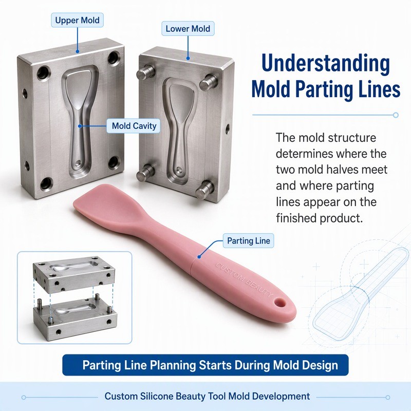
A two-plate compression mould forms the outside of the product with an upper cavity and a lower cavity. Where those two cavity edges meet, a small step is unavoidable: the steel cannot close to zero gap, and the compound needs somewhere to breathe as it fills. That meeting plane becomes the parting line on the finished part.
Change the structure and you change the line. A mould split horizontally around the widest section produces a seam at the widest circumference. Split vertically through the centre and the seam runs across the face instead. Add a third plate to form an undercut and you introduce a second line, often in a place that is much harder to hide.
This is why the position of the line is a design output, not a toolmaking accident. It should appear on the drawing as a controlled feature with a stated location and an acceptable visual weight, in the same way a radius or a wall thickness does.
In the example shown here, the tool is split so that the seam sits on the side wall of the spatula handle, where it reads as a moulded edge rather than a surface interruption. The blade, which is the part a user looks at while applying product, is formed entirely within one cavity half.
That arrangement costs nothing extra in tooling. It only requires the decision to be made before the cavity blocks are machined, and it is the single highest-value conversation a buyer can have at the mould design stage.
Mold Surface Quality Affects the Finished Silicone Surface
Silicone reproduces surface texture with unusual fidelity. A cavity polished to a fine finish yields a part with a soft sheen; a cavity left with visible machining marks yields a part that shows them, slightly softened but clearly present. This is useful when a matte, grippy surface is wanted and awkward when a uniform cosmetic finish is required.
The finishing direction matters as much as the roughness value. Polishing across a curved surface in one direction leaves a directional grain that catches light differently depending on how the part is held. On a flat silicone sponge face, that grain can read as a subtle stripe under retail lighting even though the surface is technically smooth.
Texture is also a way to manage the seam. A light, even texture across the whole part makes a thin parting line far less noticeable than the same line on a perfectly glossy surface, because the eye has more to read.
Small Mold Design Details Can Become Visible on Finished Products
Details that look trivial in CAD become visible at production scale. A 0.2 mm step at the edge of a recess, a sharp internal corner where the compound cannot fully pack, a vent slot that leaves a faint witness mark: each is small in isolation and cumulative in appearance.
The most common example on beauty tools is the transition between a soft body and a thin working edge. If that transition is designed as a hard step, the compound hesitates there, the edge fills late, and the resulting line is thicker than it needs to be. Reworking the same transition as a short taper usually produces a cleaner edge without changing the product silhouette.
How Do Parting Lines Affect the Appearance of Different Silicone Beauty Tools?
Generic mould advice stops being useful once the product shape is specific. The same parting line decision that works on a flat sponge face is wrong on a brush holder with a hollow interior, and the reasoning differs in each case.
Parting Lines on Silicone Makeup Sponges and Applicators
A silicone sponge is essentially a rounded solid with a soft, thin rim. The natural split is around the widest circumference, which places the seam exactly where the product is most visible when it stands on a vanity. It also places it on the surface that contacts foundation, so any residual film is transferred directly to the product being applied.
Two adjustments help. First, move the split slightly below the widest point so the seam sits on the lower curve, out of the primary viewing angle, and accept a marginally thicker flash line there because it is less exposed. Second, form the upper dome in a single cavity half so the working face has no seam at all. The lower edge of the sponge carries the line, and the face the customer touches stays continuous.
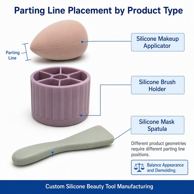
The same reasoning produces different answers across the range. On the sponge, the seam drops below the widest point. On a brush holder, it moves to the base underside or onto a moulded rib. On a spatula, it stays on the handle and away from the blade.
None of these choices is visible in a 3D render. They only become apparent on a moulded sample, which is why approving a tool from a render alone carries real risk.
Parting Lines on Silicone Makeup Brush Holders
Brush holders are typically hollow, with a base, an outer wall and internal dividers. That geometry forces the split into a less convenient place. If the holder opens upward, the line falls around the outside of the rim, which is prominent but easy to finish. If it opens downward, the line sits under the base where it is invisible, but the internal dividers then have to be formed by a core that must release without dragging.
On taller holders, the practical answer is often a split near the base, with the outer wall formed in one piece. The seam reads as a moulded foot rather than a joint, and the internal structure is formed by a core pulled vertically. Where the geometry includes a handle or an ear, that feature usually dictates the split instead, and the resulting seam should be positioned on its least visible face.
Parting Lines on Silicone Mask Brushes and Spatulas
These are the products where seam placement has the clearest functional consequence. A mask brush has a head that must feel smooth against the face and a handle that must not collect product. A spatula has a blade edge that must be thin and continuous.
For both, the workable arrangement is to form the working end within one cavity half and place the line at the transition to the handle. The transition is a natural visual break, so a faint seam there reads as a design step. Putting the line along the blade edge instead produces a thin, irregular lip exactly where the tool does its job.
What Makes Parting Line Placement Difficult in Custom Silicone Molds?
Difficulties come from geometry that refuses to cooperate with a simple two-part split. Recognising them early is cheaper than discovering them at trial.
Complex Shapes May Limit Available Parting Line Positions
An irregular curved body can only be split where a plane actually intersects the surface in a closed loop that allows both halves to release. On a shape with a pronounced waist, a recessed panel or a compound curve, there may be only one or two such planes, and neither may be visually convenient.
When that happens, the choice is between accepting a visible seam, changing the product shape slightly, or accepting a more expensive tool. All three are legitimate answers, but the decision belongs to the brand, because it trades appearance against cost.
Undercuts Can Complicate Mold Opening and Product Demolding
An undercut is any feature that prevents the part from being pulled straight out of the cavity, such as a lip that overhangs inward, a side recess, or a return on the base. Silicone is flexible, so small undercuts can sometimes be stripped over a core, but the material is stretched during that operation and the part may not return to shape cleanly.
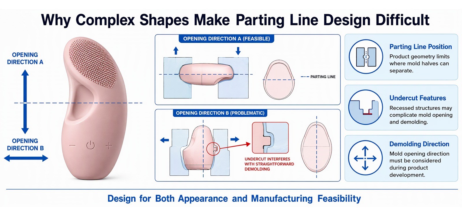
The temptation is to force demoulding by relying on silicone's elasticity. On a soft part with a shallow return this can work. On a firmer compound or a deeper undercut it produces stretched rims, whitened stress marks and parts that sit unevenly. A collapsible core, a split insert or a small design change to remove the undercut are the alternatives, and each affects both cost and seam layout.
Visible Parting Lines Must Be Balanced Against Manufacturing Feasibility
A seam can almost always be hidden by adding mould complexity. It can also almost always be made cheaper by accepting more of it. The useful question is not "can this be hidden" but "what does hiding it cost per unit, and is that cost justified by where the seam would otherwise be".
On a high-volume retail product where the tool is used daily and photographed constantly, a split insert may be worth it. On an accessory where the seam falls under a lid, it usually is not.
How Can Mold Design Improve the Appearance of Custom Silicone Beauty Tools?
The improvements that matter are mostly free at the design stage and expensive afterwards. Four are worth building into the process as a routine.
Place Parting Lines in Less Visible or Less Critical Areas
Identify the primary viewing direction of the product first, then place the seam outside it. On a brush holder that is viewed from the front and above, the underside of the base and the rear wall are both acceptable. On a sponge viewed from above, the lower curve is acceptable and the dome is not.
Refine Mold Alignment and Parting Surface Quality
A well-aligned mould produces a thin, even line that can be finished consistently. A mould that relies on operator feel produces a line that varies from part to part, and variation is far more noticeable than a uniform seam. Guide pins, a register step and a lapped sealing land are the standard measures.
Use Suitable Mold Surface Finishes for Different Product Areas
Different regions can carry different finishes within one cavity. A polished working face combined with a lightly textured body gives a clean contact surface and a forgiving exterior, and the transition between the two can be placed to reinforce the design rather than fight it.
Review the Mold Design Before Cutting Steel
A structured review before machining is the cheapest quality intervention available. It covers the product geometry and wall thickness, the intended split position, the demoulding direction, and an explicit list of which surfaces are appearance-critical.
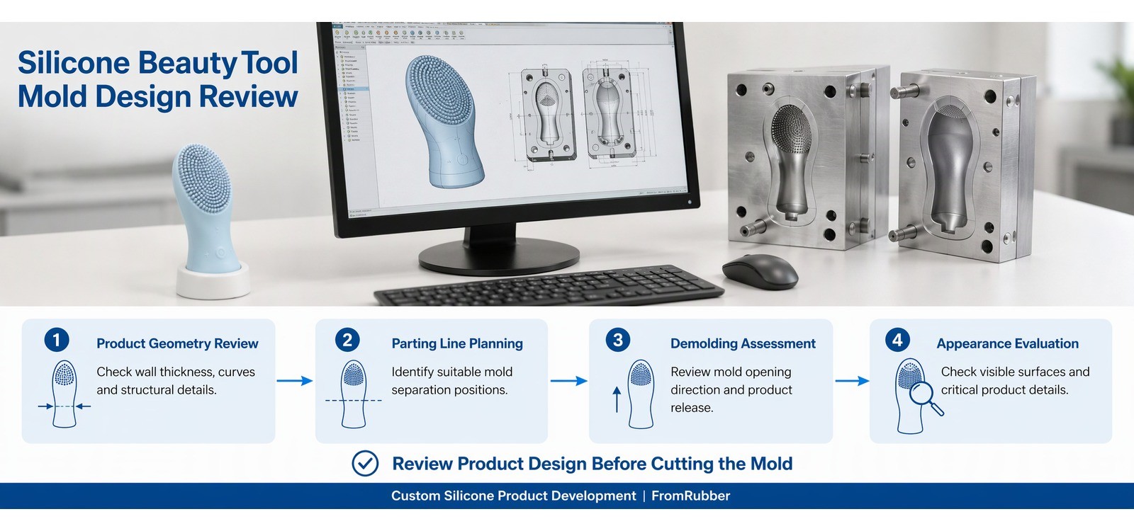
This review is also where conflicts surface. A brand may want a seam hidden on a face that the mould cannot reach without a split insert, or a wall thin enough to look refined but too thin to fill reliably. Finding that out on paper costs a meeting. Finding it out after machining costs a mould.
What Should Buyers Check When Reviewing Silicone Mold Samples?
A moulded sample is the only reliable evidence of how a tool will behave. A 3D render shows shape; a sample shows seams, texture, gloss, edge quality and demoulding marks together.
Inspect Parting Line Position on the Actual Molded Sample
Look at the part from the direction a customer will look at it. Then rotate it to the angle it will sit at on a shelf or a vanity. A seam that disappears in one orientation can be prominent in the other, and the second view is the one that matters.
Compare Surface Finish With the Approved Appearance Standard
Place the sample next to the reference you approved and view both under the same light. Gloss differences that are invisible in a meeting room become obvious in daylight or under a retail spotlight.
Check Whether Demolding Leaves Marks or Distorts the Product
Look for stress whitening near thin sections, a base that does not sit flat, or a rim that has taken a permanent set. These are demoulding symptoms, and they will be present on every unit if the tool and the compound are not matched.
Confirm That the Molded Design Can Be Repeated Consistently
Ask for parts from several cavities and from a second run. Consistency across cavities is the practical test of whether the design is manufacturable, and it is the question most likely to be skipped when a single attractive sample is on the table.
Frequently Asked Questions About Silicone Mold Parting Lines
Are parting lines normal on silicone molded products?
Yes. Any part formed by two mould halves will carry a line where they met. The variables are its position, its thickness and how consistently it can be finished, not whether it exists.
Can parting lines be hidden on custom silicone beauty tools?
They can be moved out of the primary viewing direction, or placed on a design feature where a step reads as intentional. Fully hiding a line normally requires a different mould structure, which adds cost and often adds a second seam elsewhere.
Does a more complex mold always produce better product appearance?
No. Complexity can solve one appearance problem and create another, for example by introducing a second seam or a witness mark at a split insert. The relevant comparison is cost against the visibility of the seam being removed.
Can mold design reduce visible seams on silicone products?
It can reduce how visible they are, mainly through seam placement, alignment accuracy, consistent finishing and a surface texture that gives the eye something other than the line to read.
Where the Decision Actually Belongs
Mould design decides appearance in the same way a floor plan decides how a room feels: not by decoration, but by where the walls are. For silicone beauty tools, that means settling the split position, the appearance-critical surfaces and the demoulding direction while the design is still a file, and then verifying all three on a real moulded part rather than a render.
FromRubber builds silicone beauty tools and reviews product structure and mould feasibility before tooling, which is the stage where a seam can still be moved cheaply. If you have a design in progress and want a second opinion on where the line will land, send the drawing or a reference sample and the engineers will respond with a written assessment of the split position and any features likely to complicate demoulding. WeChat or WhatsApp: +86 18676210913. Files can also be sent through the inquiry page.
About the source
FromRubber is the brand of Dongguan Bohao Electronic Technology Co., Ltd., a custom silicone and rubber parts manufacturer that produces compression-moulded components for beauty, electronics and industrial customers. The notes above come from production work on custom silicone tooling rather than from a general materials handbook. The parts discussed are grouped under custom silicone rubber parts. For a specific project, the engineering team can be reached on WeChat or WhatsApp at +86 18676210913.
Sources and further reading
- ISO 3302-1:2014, Rubber — Tolerances for products — Part 1: Dimensional tolerances, used as the common reference for moulded-part tolerance classes. ISO 3302-1:2014 standard page
- FromRubber engineering note on why parting line position drives downstream decoration accuracy
- FromRubber review of common silicone mould design mistakes
- Related note on parting line design as a flash control measure