
Custom Silicone Seals for Equipment Assemblies: How to Manage Undercuts and Thin-Wall Structures
The seal design is finished, the 3D model is signed off, and then the tooling quote comes back with a note: the undercut will need a split mould. Nobody designed a difficult part. The difficulty was created one fillet at a time.
Undercuts and thin walls are usually treated as two separate manufacturing problems. They are not. Both are questions about how far the material must move during demoulding, and what happens to the material while it moves. Once you look at them that way, most of the design decisions that matter become visible before a tool is cut — and most of the ones that cause trouble are not the depth of the undercut but the geometry immediately around it.
This is not an argument that complex seals cannot be moulded. Flexible silicone can do things rigid plastics cannot. It is an argument that the ability to stretch is a budget, and the budget is spent at the transitions.
Why Do Undercuts Create Challenges in Custom Silicone Seal Manufacturing?
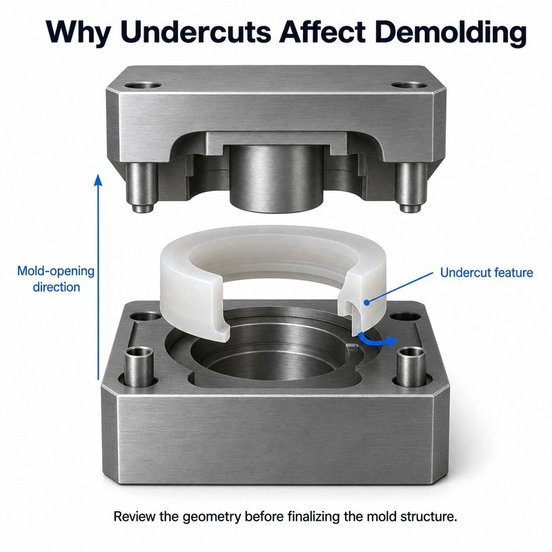
How Undercuts Affect Mold Opening and Product Removal
An undercut is any feature that lies behind the mould's opening direction. On a rigid part it is a hard stop: the steel cannot pass through the material. On a silicone part it is not a stop but a tax — the material must deform enough to let the core past, then recover.
The tax is paid in local strain. A retaining lip with a generous outer radius, a short depth and a thin supporting wall bends outward easily and springs back. The same lip with a square internal corner and a thick backing wall concentrates the strain into a narrow band, and that band is where the part tears or takes a permanent deformation.
Why Deep Internal Grooves Can Be Difficult to Demold
A deep internal groove is harder than a shallow one for a reason that is not obvious from the section drawing: the material has to slide along the core for the full depth of the groove before it is free. Friction between silicone and polished steel is not negligible, and it rises as the contact pressure rises. A deep groove with parallel walls grips the core along its whole length.
The consequence appears as a stretched or distorted groove after demoulding, and later as a seal that does not sit where the drawing says it should.
When Does an Undercut Require a Different Mold Structure?
Sometimes the answer is not a better fillet. If the feature wraps a full circumference and is deep relative to the part's stiffness, the options are a split cavity, a collapsing core, a removable insert, or a demoulding method that opens the part before ejection.
Air-assisted demoulding is one route that has been used specifically for flexible parts with large undercuts: air is introduced through the core to expand the part while it is being ejected, so the undercut opens instead of being dragged. It is used where conventional strippers would deform the part, and it is a mould-design decision rather than a material one.
What Manufacturing Problems Can Thin-Wall Silicone Seal Structures Cause?
Incomplete Material Filling in Narrow Sections
A thin section is a narrow gate for the material on its way to somewhere else. Silicone compounds are viscous before cure, and the pressure available to push material through a thin web falls off with distance. The result is a short shot, or worse, a section that looks filled but carries a weld line where two flow fronts met.
Weld lines matter in a seal because they are mechanically weaker than the surrounding material and they are invisible after demoulding. A thin sealing lip with a weld line in it will pass a dimensional check and fail in service.
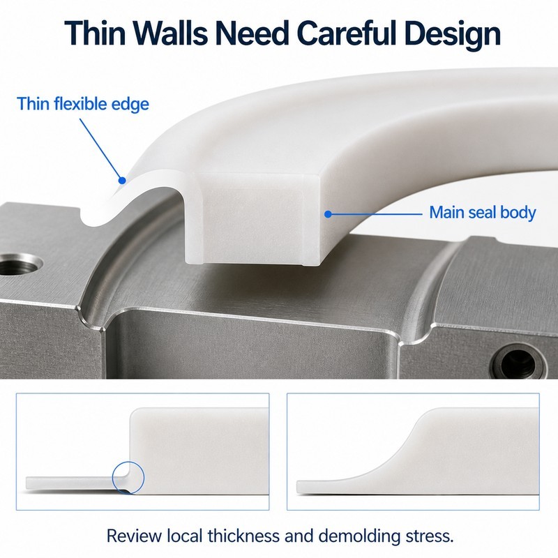
Tearing Around Thin Edges During Demolding
Thin edges tear because the stress of demoulding is concentrated exactly where there is least material to carry it. Two things decide whether it happens: the direction the part is pulled relative to the thin edge, and whether the edge is supported by a thicker section immediately behind it.
A thin lip that is pulled along its length survives. The same lip pulled across its width, with a square step behind it, tears at the step. The fix is usually a taper rather than a thickness change: give the material a path to follow.
Deformation After Mold Release
Silicone is elastic, not rigid, so a moulded part can come out correct and then change shape. Thin sections cool and recover faster than thick ones, and a part with an uneven wall distribution will curl toward the thicker side as it relaxes. If the part is packed or stacked while still warm, the deformation becomes permanent.
This is a process problem with a design component: parts with strongly uneven wall sections need fixtures, trays or a settling step, and that cost belongs in the quote rather than in the first production run.
How Should Designers Balance Undercut Geometry and Demolding Feasibility?
Review Undercut Depth and Direction Before Tooling
Depth alone is a poor predictor of difficulty. What matters is the ratio between the undercut depth and the radius of the material that has to bend around it. A shallow undercut with a sharp transition is harder than a deeper one with a long, generous lead-in.
Direction matters just as much. An undercut that can be reached along a parting direction costs nothing; the same feature rotated a few degrees becomes a side action. Checking the tooling direction at the modelling stage is cheaper than checking it at the first sample.
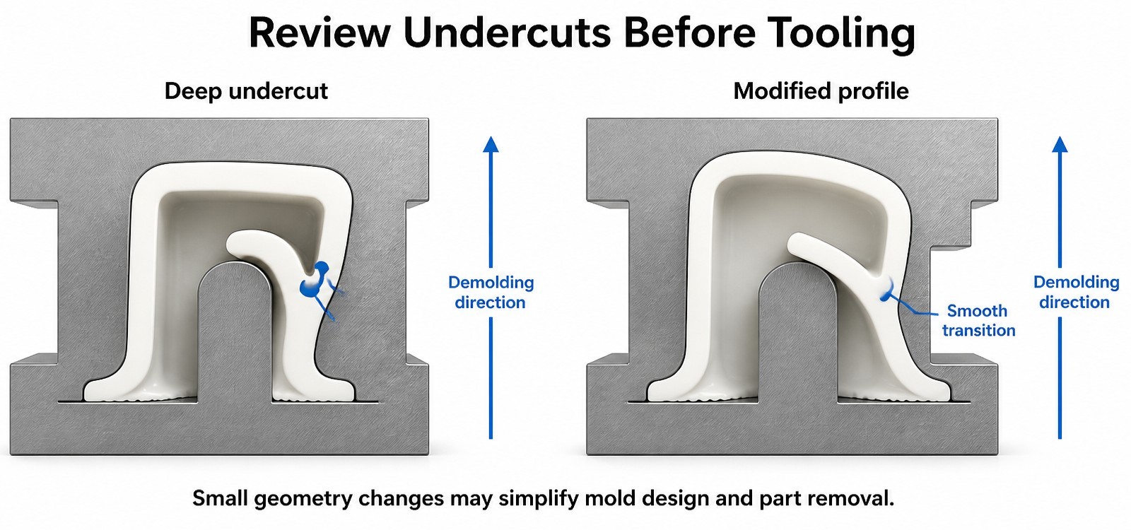
Use Rounded Transitions Instead of Sharp Internal Corners
A sharp internal corner is a stress raiser twice over: it concentrates strain during demoulding, and it becomes the initiation point for a tear in service. In a seal, that corner is also difficult to fill cleanly, so it may carry a void as well as a stress concentration.
A radius costs nothing in the model and changes the demoulding behaviour of the whole feature. Where a radius cannot be added — because the corner is a functional edge — the usual answer is to move the parting line so the sharp edge is formed by steel rather than by a thin wall.
Consider Whether the Retaining Feature Can Be Simplified
Many retaining features exist because they were drawn once and copied three times. A full circumferential rib, a deep groove and a hook often do the same job as a shallower rib and a lead-in chamfer. The test is whether the feature has to resist a specific load, or whether it only has to keep the part in place during assembly.
If it is the second, a smaller feature will usually do, and it will be cheaper to tool and more consistent to mould.
| Feature | Demoulding consequence | Design response |
|---|---|---|
| Deep undercut with a sharp internal corner | Strain concentrates in a narrow band and the part tears or distorts | Shallower lip, longer lead-in radius |
| Thin lip with an abrupt step behind it | The step tears while the part is stripped | Taper the transition instead of stepping it |
| Parting line crossing a sealing face | The witness mark becomes a leak path | Move the parting line to a non-sealing edge |
How Can Thin-Wall Sections Be Made More Production-Friendly?
Avoid Abrupt Changes in Wall Thickness
An abrupt step from thin to thick does three things: it creates a flow restriction, a stress concentration and a shrinkage difference. All three land at the same place, which is why the step is where parts fail.
A taper over several times the wall thickness costs a little material and removes most of the problem. In a sealing lip, the taper also acts as a hinge, which is often functionally desirable.
Review the Connection Between Thin Walls and Adjacent Thick Sections
The junction between a thin lip and a thick body is the highest-risk area in a moulded seal. The thick section cures and shrinks more slowly; the thin section is already set. The result is a built-in stress that can pull the lip out of position or leave it wavy.
The practical answer is often a cored-out thick section: reduce the mass behind the lip while keeping the outer geometry, so the two sections cure at more similar rates.
Check Whether Local Reinforcement Is Needed
Not every thin area should be thickened. Thickening a sealing lip makes it stiffer, which can stop it conforming to the mating surface — solving a moulding problem by creating a sealing problem. Local reinforcement belongs behind the lip, not in it: a small rib on the non-sealing face adds support without changing the contact geometry.
How Do Silicone Material Properties Affect Complex Seal Structures?
Selecting Hardness for Demolding and Functional Flexibility
Softer compounds deform more easily and demould more forgivingly, which is why "use a softer material" is the standard answer to a difficult undercut. It is only half right. A softer compound also extrudes more under compression, takes set more readily at temperature, and gives less contact pressure for the same squeeze.
For a complex seal, hardness should be chosen for the sealing function first, and the undercut geometry adjusted to suit. Reversing the order produces a part that moulds easily and seals poorly.
Considering Tear Resistance Around Narrow Features
Tear resistance is a compound property, but whether it matters depends on geometry. A material with good tear resistance in a thick section can still tear at a thin edge, because the failure is driven by the local strain rather than by the bulk property. This is why tear test data alone does not predict demoulding behaviour — the test piece is not the part.
The useful approach is to mould the real geometry and inspect the transition, not to select a compound on a data sheet figure.
Matching Material Performance to the Equipment Environment
A seal that survives demoulding but swells in the media it seals has solved the wrong problem. Temperature, fluid, cleaning agents and compression all belong in the material decision, and they usually narrow the compound more than the mechanical design does. Silicone is broad in temperature and narrow in oil resistance; that single fact eliminates it from many equipment seals before the undercut is even discussed.
What Should Be Evaluated Before Approving a Custom Silicone Seal Mold?
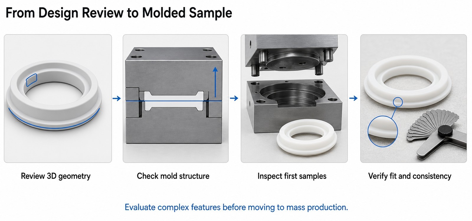
Review the 3D Model and Critical Cross-Sections
A 3D model shows what an outline drawing hides: whether the undercut is reachable, where the wall thickness changes, and whether the sealing lip has a hinge or a step behind it. Slice the model through the lip, the retaining feature and the thinnest section, and look at those slices as if they were the mould.
Confirm the Proposed Mold Structure
Ask where the parting line will be. Then ask what it crosses. A parting line on a cosmetic surface leaves a witness mark; a parting line on a sealing face leaves a leak path that no amount of compression will close. If the answer is "we will see at tryout", the design review has not happened.
Evaluate First Samples for Filling, Tearing and Deformation
Check the first samples at the transitions, not in the middle of the part. Look for short shots at thin extremities, whitening or stress marks at the lip root, and any distortion that appears after the part has cooled. Measure the part cold and again after a day; a dimension that moves is a process problem that will return in production.
Confirm Repeatability Before Mass Production
One good sample proves the tool can make a good part. It does not prove the tool can make ten thousand identical parts. Run a short batch, measure the critical sections across the batch, and confirm that the process window is wide enough to survive a shift change.
Custom Silicone Seal Design and Mold Development at FromRubber
FromRubber has run custom silicone moulding in Dongguan since 2010, with a seven-machine CNC tool shop and 32 compression moulding machines (30 vacuum-assisted, 2 plate presses) across two plants, working to IATF 16949:2016, ISO 9001:2015 and ISO 14001:2015. Complex seals — retaining lips, thin diaphragms, stepped sections — are a routine part of that work, and the useful part of the conversation usually happens before the tool drawing.
In practice, that means reading the 3D model for the three things that decide feasibility: where the material has to strain, where the parting line lands, and which section will be hardest to fill. Where a feature is genuinely difficult, the options are presented as options — a geometry change, a different mould structure, or a demoulding method — rather than as a single quotation that hides the risk.
We will not claim that any geometry can be moulded without change. Some cannot, and saying so at the drawing stage is cheaper for everyone than saying it after tryout.
Frequently Asked Questions About Custom Silicone Seal Manufacturing
Can silicone seals be manufactured with undercuts?
Yes, and often without side actions, because silicone can deform enough to release. Whether it can be done reliably depends on the depth of the undercut relative to the material's thickness and the radius at the transition, not on the presence of the undercut alone.
What happens if a silicone seal has very thin walls?
Thin sections are harder to fill, harder to demould without tearing, and more likely to distort after release. They also concentrate stress in service, so a thin lip that survives the mould may still fail in the field at the same transition.
How can I prevent thin silicone edges from tearing during demolding?
Give the material a path: taper the transition instead of stepping it, put the thin edge where it can be pulled along its length, and place the parting line so the sharp edge is formed by steel. Air-assisted demoulding is an option where the undercut is large and the part is flexible.
Can a silicone seal design be modified to simplify mold structure?
Usually. Shallower retaining features, larger transition radii and a repositioned parting line often remove the need for a split cavity without changing what the seal does. The change has to be reviewed against the sealing function, not only against the tooling.
Should I provide a 3D drawing when requesting a custom silicone seal?
A 3D model is far more useful than an outline, because it shows the undercut direction, the wall distribution and the transitions that decide feasibility. A 2D section plus a sample can work, but it usually costs a round of questions.
Design the Release, Not Just the Seal
Every complex seal has two jobs: hold pressure in service, and come out of the tool intact. Both are decided by the same geometry, and the second one is much cheaper to fix before the steel exists.
If you have a seal with an undercut or a thin section that has been quoted as difficult, send the 3D model. We will tell you where the strain is and what it would take to remove it. WeChat and WhatsApp: +86 18676210913.
Sources
- Mold Design Using Air Jets Solves Molding Challenges, MoldMaking Technology — air-assisted demoulding of flexible parts with large undercuts.
- Elastic recovery after compression in HNBR at low and moderate temperatures, Polymer Testing 61 (2017), SINTEF — elastic recovery and permanent set in elastomer seals.